Chapter 3 Web Interface of RDU501
RDU501 Intelligent Monitoring Unit User Manual
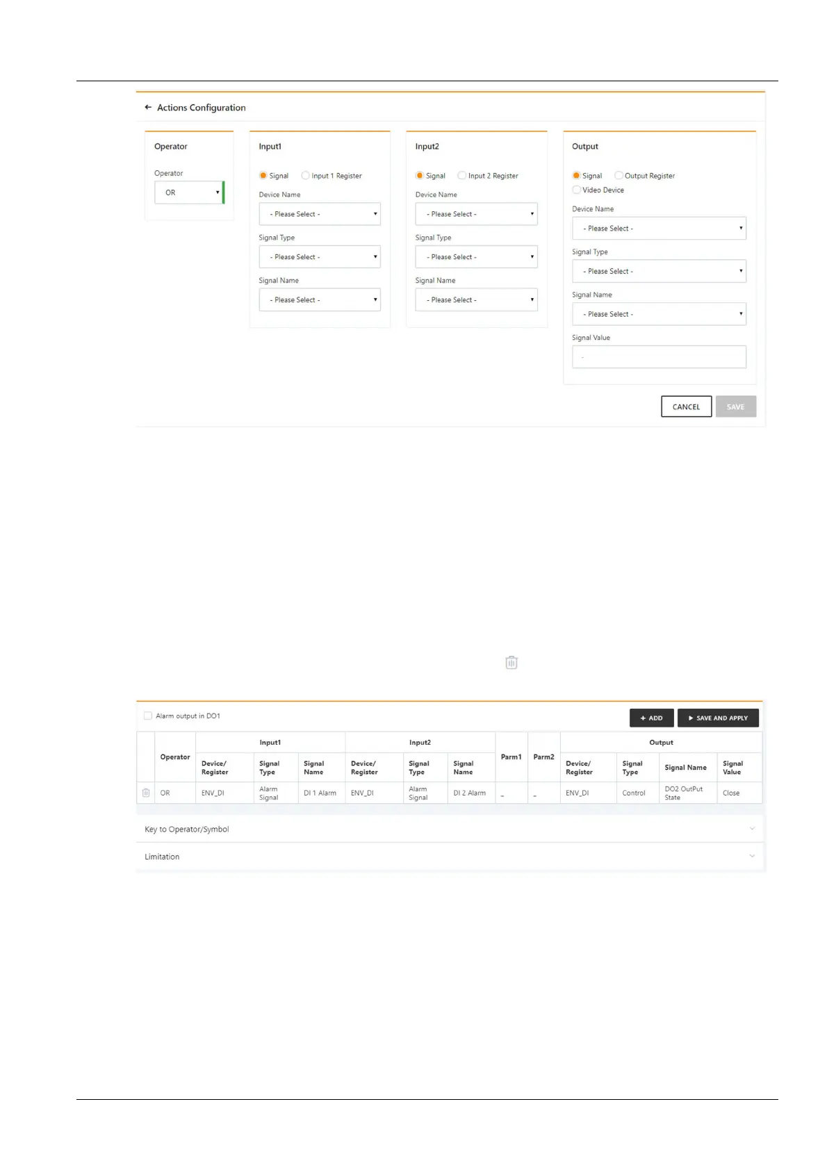
Figure 3-129 Alarm linkage configuration 2
First, select an operator, for example, "OR", the expression is "Signal 1 [Input 1 Register] or Signal 2 [Input 2
Register] = Output Signal [Output Register, Video Device]".
Second, when the input or output parameter in the expression is selected as the signal, first select the device name in
the Device Name drop-down list, then select the signal type in the Signal Type drop-down list, and finally select the
signal name in the Signal Name drop-down list. Input 1, output 2, and output signals may be any of the signals
available in RDU 501.
Finally, when the parameter in the expression is selected as a Register, you need to select the name of the
corresponding register, such as R(0), R(1), and so on.
Click the Save button to add a new alarm linkage expression, otherwise click the Cancel button.
If you click the Save button, as shown in Figure 3-130, the alarm linkage expression has been added, click the
Saving effective button to make it effective. Click the Delete button to delete the alarm linkage expression and
click the Saving effective button to make it effective.
Figure 3-130 Alarm linkage configuration 3