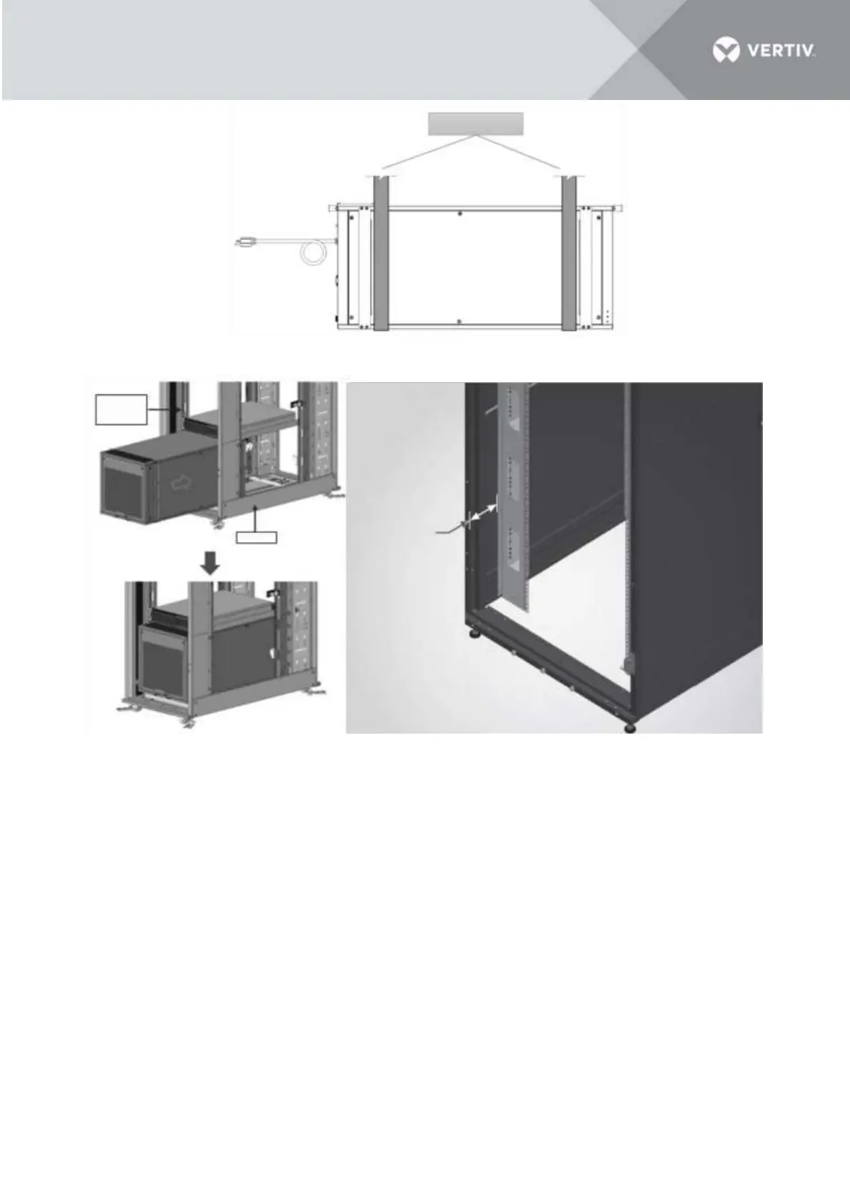
Figure 3-8 Lifting straps
Figure 3-9 Mounting the VRC into the rack
4. The distance between A-pillar and C-pillar (or between B-pillar and D-pillar) is 737 mm (29’’). If the
cabinet space is suitable, then install the C-pillar and D-pillar back again onto the unit body casing. If
not, then only installing A-pillar and B-pillar is OK.
5. Firmly secure A-pillar, B-pillar, C-pillar and D-pillar on the cabinet column with 2 M6x12 screws
(fastened with cage nuts) per pillar. Torque = 5.6 Nm (4.13 lb-ft).
NOTES:
• Ensure that the installation direction of pillars is correct. And ensure the VRC unit is installed
horizontally, otherwise high-water level alarms may be triggered incorrectly.
3.4 Connecting the Accessories.
If the unit must be placed in an environment where the hot air from the condenser duct needs to be
extracted from the room and discharged at a suitable pre-determined location, an air duct is provided as a
part of the accessories shipped with the unit and can be connected to the condenser discharge side.
 Loading...


