Service Manual Indicator JIK-6 Page 11
Chapter III Various Assemblies and Relevant Illustrations
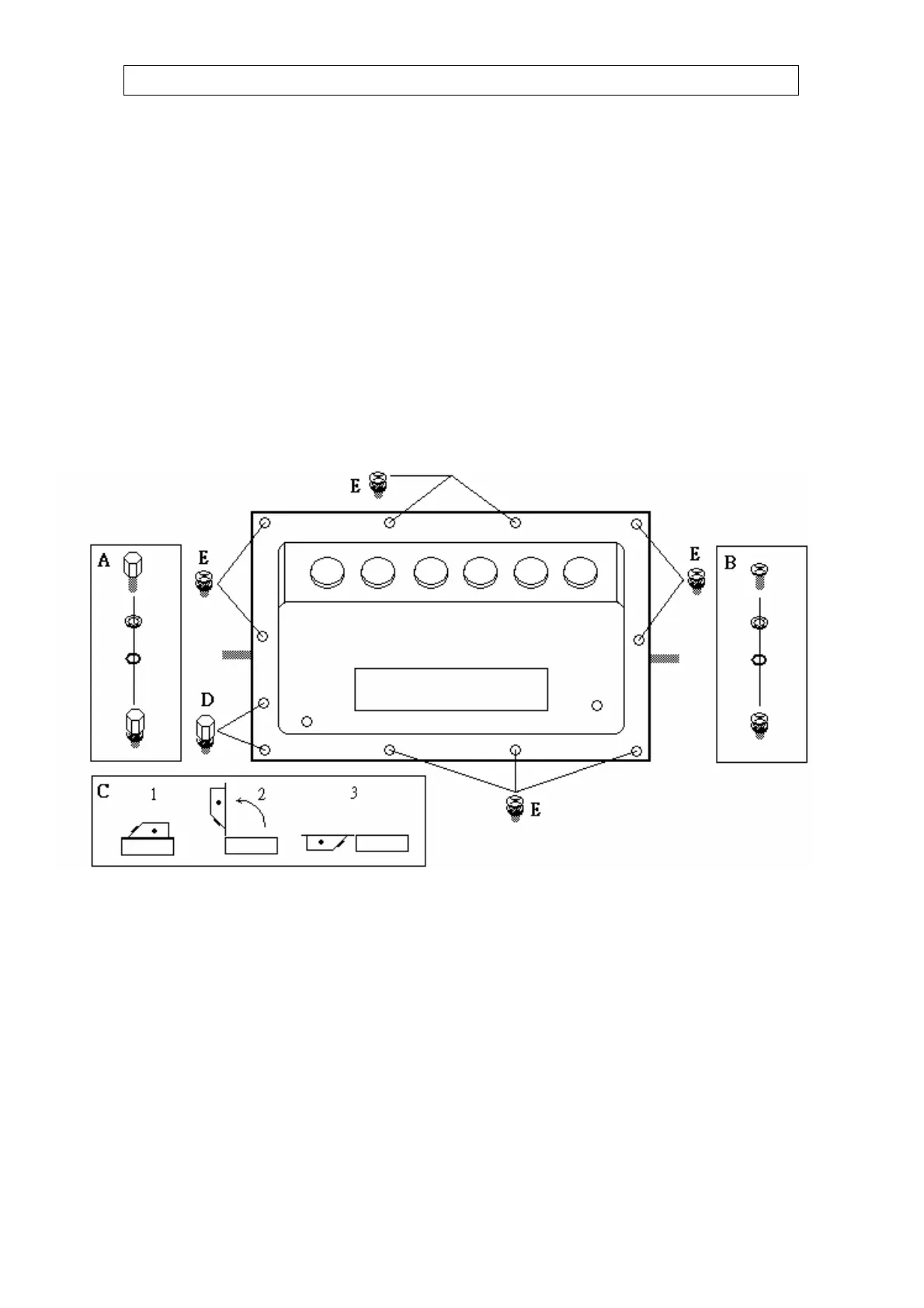
3-1 Back Cover Assembly and Disassembly
Disassembly Steps:
1. Put the display head as shown in figure below, loosen the waterproof connector first to avoid damage of
contacts on the board, unscrew the fastening screws (position “E” as shown in figure below) by use of a
cross head screwdriver, and unscrew the two Allen screws (position “D” as shown in figure below) by use
of a 5mm Allen wrench or socket wrench.
2. As per the steps shown in Fig. C, remove the back cover and place it properly.
Assembly Steps:
1. Screw in the fastening screws by use of a cross head screwdriver, and screw in the two Allen screws by
use of a 5mm Allen wrench or socket wrench.
2. Special attention must be paid to check if every screw for display head of waterproof series is locked
tight. The screw-in torque shall be 5~7kg, and the screws at the four corners must be fastened at last (no
limitation for fastening order of others).
Note: As shown in Fig. A &B below, all screws of waterproof series have a stainless steel gasket and a
rubber gasket, which must be secured properly to avoid leakage.
(Take the waterproof model with built-in battery as the example)

 Loading...