Getting Started
Page 5-2 Mastertech 3100 Operator’s Manual
CONNECTING THE TESTER TO THE
VEHICLE
The Mastertech kit contains the following cables and adapters to connect the tester to the vehicle.
• Data Link Connector (DLC) Cable
• DC Power Cable
• GM 12/14 Pin DLC Adapter
• Ford 7/14 Pin Adapter
• Chrysler 6/14 SCI DLC Adapter
• GM 5-Pin Adapter
•GM Pin-E Adapter
Refer to the Repair Manual or the electrical wiring diagram for the vehicle you are testing to determine the
location and type of Data Link Connector (DLC) provided on the vehicle.
1. Connect the 26-pin end of the DLC cable to the bottom of the tester, then tighten the screws.
2. Depending on the vehicle make and the tests to be performed, connect the appropriate vehicle adapter to
the end of the DLC cable.
3. Connect the other end of the vehicle adapter to the vehicle DLC.
4. Connect RS232 and Instrumentation Port devices that you plan to use to the Mastertech. RS232 devices,
such as a printer, are connected to the bottom left side of the tester. Instrumentation devices such as the
Diagnostic Test Lead connect to the bottom right side. The RS232 and I/P cable connectors are 10-pin
RJ45 “phone” plugs that are keyed so they fit only the correct connector.
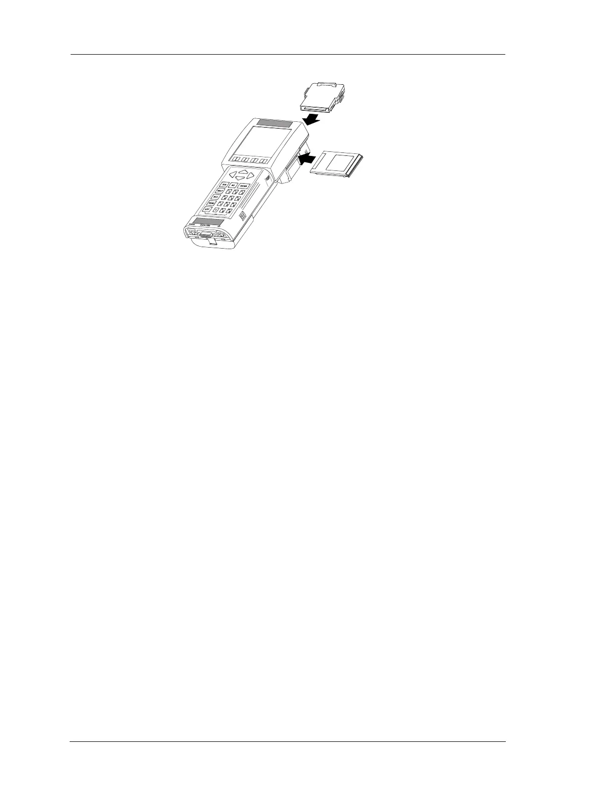
PROGRAM
CARD
APPLICATION
CARTRIDGE
FIGURE 5-1. Installing Program Card and Cartridge