EasyManua.ls Logo

Vicon Extra 232 - User Manual

Vicon Extra 232
18 pages
Print Icon
To Next Page IconTo Next Page
Loading...
Extra 224 - 228 - 232
Assembly instruction
Translation of the original assembly instruction
Edition 11.2012
Date of print 04.2012
Language EN
Document number 24020202EN
Index number 2011-12
Question and Answer IconNeed help?

Do you have a question about the Vicon Extra 232 and is the answer not in the manual?

Summary

Preface

Meaning of the Symbols

Explains the meaning and importance of warning symbols used in the manual for safety and operational guidance.

Torque Moment Specifications

Provides a table of torque values for various bolt sizes and quality grades, crucial for secure assembly.

Assembly Instructions

Initial Machine Preparation

Steps for unpacking, loosening fasteners, and removing major components like the cutterbar and hitch.

Three-Point Hitch Mounting

Instructions for lifting, positioning, and securing the three-point hitch assembly to the main unit.

PTO Outlet Protection and Support Fitment

Attaching the protection cap to the PTO outlet and fitting the support component as per diagram.

Bracket, Lock Plate, and Brace Installation

Mounting a bracket, securing a lock plate, and fitting a brace with specific orientation notes.

Brace Securing and Pawl Check

Finalizing brace attachment, fitting another bracket, noting washer placement, and verifying pawl position.

Hydraulic Cylinder Installation

Attaching and securing the hydraulic cylinder using specified bolts and nuts.

Stabilizer Spring and Nut Assembly

Installing the stabilizer spring, pressure ring, and securing the nut with pins.

Spring Pre-tightening and Lubrication

Fitting bushing, washer, circlip, lubricating the spindle, and pre-tightening the spring.

Support Leg and Locking Mechanism

Attaching the support leg, fitting the locking pawl with a pin, and connecting the string.

Hydraulic Hose Securing and Skid Mounting

Routing and securing the hydraulic hose, then mounting the skid to the machine.

Guard Installation

Fitting protective guards, with specific instructions noted for Model 232.

Tarpaulin Frame Attachment

Instructions for fitting the rear and front tarpaulin frames and a related bracket.

Tarpaulin Placement and Fastening

Positioning the tarpaulin over the frame and securing it with end frames and edging.

Tarpaulin Securing and Lifting Pin Installation

Final securing of the tarpaulin, fitting a pin, and installing lifting pins with torque specification.

Final Component Installation: Lifting Pins and PTO Shaft

Installing the lifting pins and the PTO shaft, completing the assembly process.

Overview

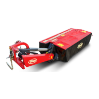
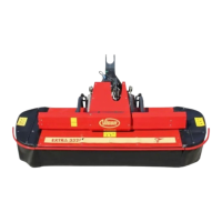
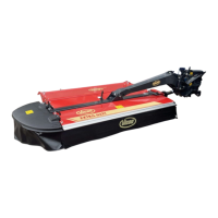
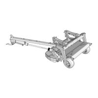
This document provides assembly instructions for the Vicon Extra 224, 228, and 232 models, which appear to be agricultural machinery, specifically mowers or similar implements, given the references to a cutterbar, P.T.O. (Power Take-Off) shaft, and tarpaulin. The manual is a translation of the original assembly instructions, dated November 2012, with a print date of April 2012. It is published by Kverneland Group Kerteminde AS, a company specializing in agricultural machinery.

Function Description

The primary function of the device is to perform agricultural tasks, likely mowing or conditioning, as indicated by the presence of a cutterbar and a P.T.O. shaft for connection to a tractor. The assembly instructions detail the process of reassembling the machine after it has been dismantled for transport from the factory to the user. This involves attaching various components such as the three-point hitch, transmission, support legs, guards, tarpaulin, and lifting pins. The machine is designed to be robust, with specific torque settings for bolts to ensure secure and safe operation. The inclusion of a tarpaulin suggests a need to protect internal components or harvested material during operation or storage. The hydraulic cylinder and stabilizer spring indicate mechanisms for adjusting the machine's position or tension during use.

Important Technical Specifications

The manual provides critical technical specifications, primarily focusing on bolt quality and torque moments, which are essential for safe and correct assembly.

  • Bolt Quality and Torque Moments: A detailed table specifies torque values (in Nm and ft lbs) for various bolt dimensions (M5 to M24) across different bolt qualities (4.6, 5.8, 8.8, 10.9, 12.9). These values are for black and/or galvanized, ungreased bolts tightened on a smooth surface or a plain washer. For example, an M16 bolt of quality 8.8 requires 197 Nm (141 ft lbs) of torque, while an M24 bolt of quality 12.9 requires 1120 Nm (800 ft lbs). This precision is crucial for structural integrity and preventing loosening during operation.
  • Specific Fasteners: The instructions list specific fasteners used for different components, including:
    • M8 x 20 bolts for the protection cap.
    • M16 x 55 bolts for the bracket.
    • M8 x 30 bolts and M8 lock nuts for securing the hydraulic cylinder.
    • M12 x 40 bolts and M12 lock nuts for the support leg and tarpaulin frames.
    • M10 x 25, M10 x 30, M10 x 19 bolts, and M10 lock nuts for various guards and tarpaulin fastenings.
    • M16 x 110 bolts and M16 lock nuts for lifting pins, with a specified torque of 225 Nm (165 ft lbs).
  • Washer Dimensions: Various washers are specified, such as Ø30 x Ø16.5 x 15, Ø30 x Ø16.5 x 10, Ø35 x Ø21 x 21, Ø13-Ø24x2.5, Ø10.5-Ø20x2, Ø10.5-Ø30x2.5, and Ø17-Ø30x3, indicating precise fitting requirements.
  • Pin Dimensions: Pins of different sizes are used, including Ø20 x 90, Ø6 x 30, Ø3.5 x 30, Ø6 x 30, and Ø20 x 70.
  • Spring Pre-tension: For the stabilizer spring, specific pre-tension lengths are given for each model:
    • Model 224: 80 mm (3").
    • Model 228: 150 mm (6").
    • Model 232: 120 mm (4 3/4").

Usage Features

The assembly process itself highlights several usage features:

  • Modular Design: The machine is designed to be dismantled into main components for transport, indicating a modular construction that facilitates shipping and potentially field repairs.
  • Tractor Compatibility: The mention of a three-point hitch and P.T.O. shaft confirms that the device is designed to be attached to and powered by a standard agricultural tractor.
  • Hydraulic Operation: The presence of a hydraulic cylinder and hydraulic hose indicates that certain functions of the machine, likely lifting or adjusting, are hydraulically controlled, offering ease of operation from the tractor cabin.
  • Adjustability: The stabilizer spring with adjustable pre-tension suggests that the machine's ground pressure or cutting height can be adjusted to suit different field conditions or desired outcomes.
  • Protection: The inclusion of guards and a tarpaulin implies a design consideration for protecting both the machine's internal components from debris and potentially protecting harvested material.
  • Safety Features: The manual emphasizes safety with warning symbols and instructions, indicating that the machine is designed with safety in mind, requiring proper assembly and operation to prevent accidents.

Maintenance Features

While primarily an assembly manual, some aspects hint at maintenance considerations:

  • Lubrication: The instruction to "Lubricate the spindle thoroughly" suggests that regular lubrication of moving parts, such as the spindle, is a key maintenance requirement to ensure smooth operation and longevity.
  • Component Replacement: The detailed listing of fasteners and components implies that individual parts can be replaced if damaged or worn, facilitating repairs rather than requiring full machine replacement. The emphasis on using "only original parts" for safety reasons further supports this.
  • Inspection Points: Instructions like "Check that the pawl is in the position shown" and "Make sure that the transmission is properly supported" during assembly suggest critical inspection points that would also be relevant during routine maintenance checks.
  • Protection of P.T.O. Outlet: Mounting a protection cap at the P.T.O. outlet indicates a design feature to protect this critical interface from dirt and damage when not in use, contributing to its maintenance and lifespan.
  • Access for Assembly/Maintenance: The sequential steps for assembly, including lifting and swinging components, suggest that the machine's design allows for reasonable access to various parts for both initial assembly and subsequent maintenance.

Vicon Extra 232 Specifications

General IconGeneral
BrandVicon
ModelExtra 232
CategoryFarm Equipment
LanguageEnglish

Related product manuals