Installation Guide
41
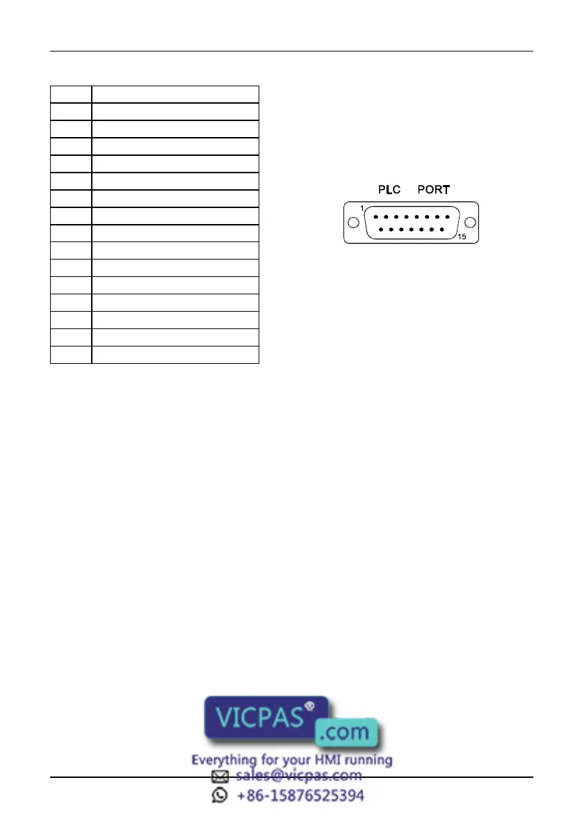
Figure 37 - PLC Port connector and pin assignment
The communication cable must be chosen for the type of device being connected.
PC/Printer Port
The function of the PC/Printer Port depends on the mode of operation of the panel.
Configuration Mode programming port
Operation Mode, UniNET Server connection to UniNET
Operation Mode, UniNET not active or Client node connection to serial printer
Only RS232 signals are available on the PC/Printer Port. The connector is a D-15 pin
female. Pin assignment is shown in the table below.
Pin Description
1 Frame Ground
2 RXD
3 TXD
4 +5 V output (Max 100mA)
5 GND
6 CHA-
7 CHB-
8 TX+ 20 mA
9 TX- 20 mA
10 RTS
11 CTS
12 RX+ 20 mA
13 RX- 20 mA
14 CHA+
15 CHB+