EasyManuals Logo

Victaulic FireLock 751 Series Installation, Maintenance, & Testing Manual

Victaulic FireLock 751 Series
18 pages
To Next Page IconTo Next Page
To Previous Page IconTo Previous Page
Page #10 background imageLoading...
Page #10 background image
Series 751 FireLock
®
European Alarm Check Valve Stations
9
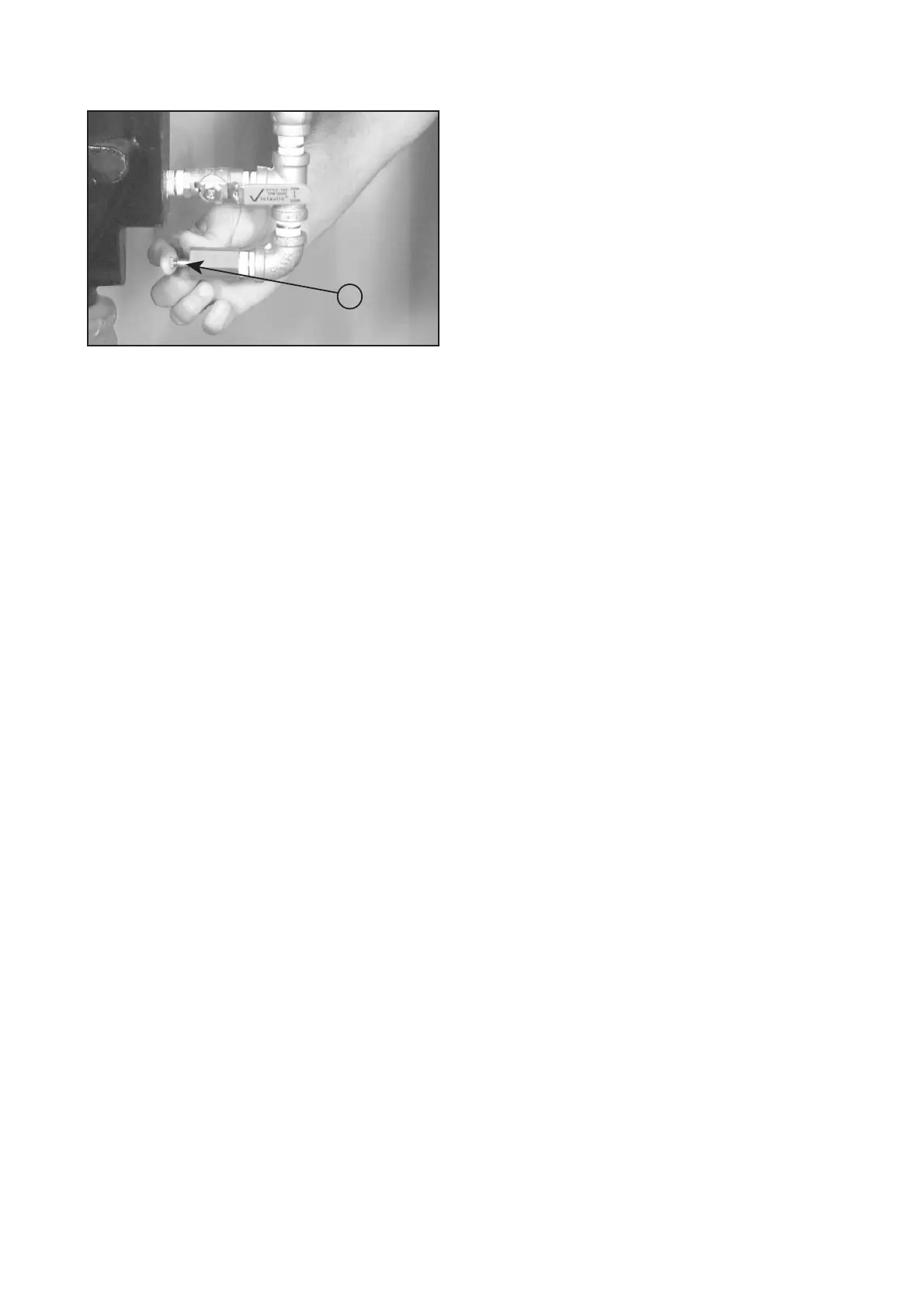
6. Push in the plunger on the restricted orifice/alarm line
drain (7), as shown above.
7. Verify that no water is flowing from the restricted orifice/
alarm line drain (7).
8. Notify the authority having jurisdiction, remote station
alarm monitors, and those in the affected area that the valve is
back in service.
9. Provide test results to the authority having jurisdiction, if
required.
7

Other manuals for Victaulic FireLock 751 Series

Questions and Answers:

Question and Answer IconNeed help?

Do you have a question about the Victaulic FireLock 751 Series and is the answer not in the manual?

Victaulic FireLock 751 Series Specifications

General IconGeneral
BrandVictaulic
ModelFireLock 751 Series
CategoryControl Unit
LanguageEnglish

Related product manuals