Series 751 FireLock
®
European Alarm Check Valve Stations
3
INTRODUCTION
The following instructions are a guide for proper installation of Victaulic Series 751 Alarm Check Valves. These instructions involve pipe
that is properly prepared and grooved in accordance with current Victaulic specifications.
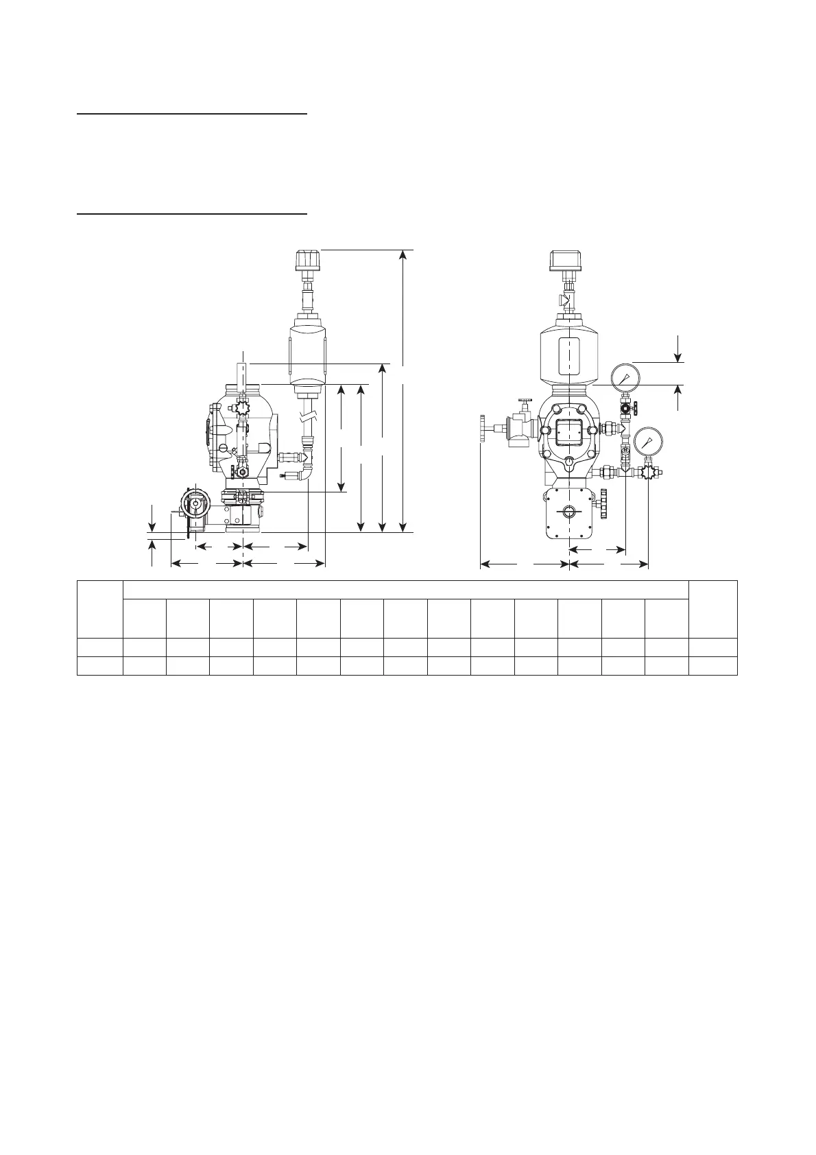
TRIM DIMENSIONS
Valve
Size
Dimensions – centimeters Approx.
Weight
Each
kgA*
A
1
B
B
1
CDEFGH I JK
DN100 38,18 50,66 59,00 202,00 16,13 22,33 24,45 28,68 7,00 19,33 33,00 33,00 7,22 54,0
DN150 40,64 56,32 61,00 206,00 18,60 25,48 33,00 38,00 – 20,30 36,00 38,00 3,20 69,0
*The “A” dimension is the measurement from the top of the valve body to the bottom of the valve body (takeout dimension).
NOTE: Overall height “B” is greatest height if optional retard chamber is not installed.
E
F
C D
H
A
A
1
B
1
B
J I
G
K

 Loading...


