Series 751 FireLock
®
European Alarm Check Valve Stations
5
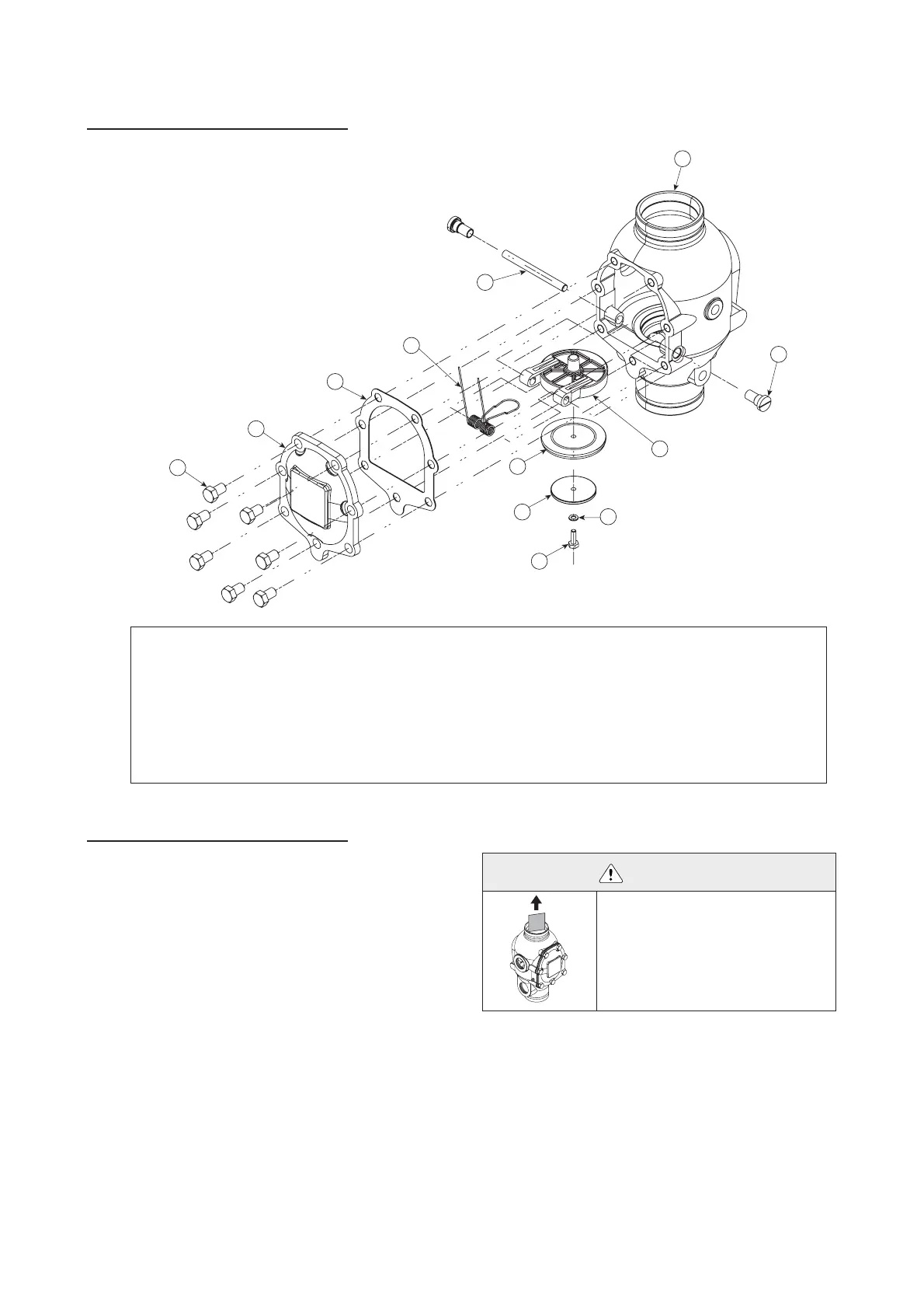
EXPLODED VIEW DRAWING – INTERNAL VALVE COMPONENTS
IMPORTANT INSTALLATION INFORMATION
1.
Before installing the Series 751 Alarm Check Valve, flush
the water supply piping thoroughly to ensure that no foreign ma-
terial is present.
2.
The Series 751 Alarm Check Valve MUST NOT be located
in an area where the valve is subject to freezing temperatures or
physical damage.
3.
It is the owner’s responsibility to confirm material compat-
ibility of the Series 751 Alarm Check Valve, trim, and associated
accessories when a corrosive environment or contaminated wa-
ter is present.
4.
Series 751 Alarm Check Valves MUST be installed in the
vertical position only. The arrow on the body must point upward,
and the arrow on the swing check valve in the bypass line must
point upward.
5.
The Series 752 Retard Chamber should be installed in
variable pressure applications. Victaulic provides specific trim
drawings for installations that involve a Series 752 Retard Cham-
ber.
6.
Confirm that all installation information is available.
7.
Remove all plastic caps and foam spacers from the valve.
8.
Install the Victaulic Series 751 Alarm Check Valve in ac-
cordance with the applicable trim drawings. Make sure the trim
drawing matches the system’s requirements (i.e. retard cham-
ber for variable pressure installations).
BILL OF MATERIALS
1 Valve Body 7 Seal-Retaining Ring
2 Clapper Shaft Retaining Bushing (Qty. 2) 8 Bolt Seal
3 Clapper Shaft 9 Seal Assembly Bolt
4 Clapper 10 Cover Plate Gasket
5 Clapper Spring 11 Cover Plate
6 Clapper Seal 12 Cover Plate Bolts (Qty. 7)
1
12
11
4
3
2
10
6
7
9
5
8
CAUTION
• Make sure foam spacers are removed before
attempting to install the valve.
Failure to follow this instruction could cause
improper valve operation, resulting in serious per-
sonal injury and/or property damage.

 Loading...


