Series 751 FireLock
®
European Alarm Check Valve Stations
13
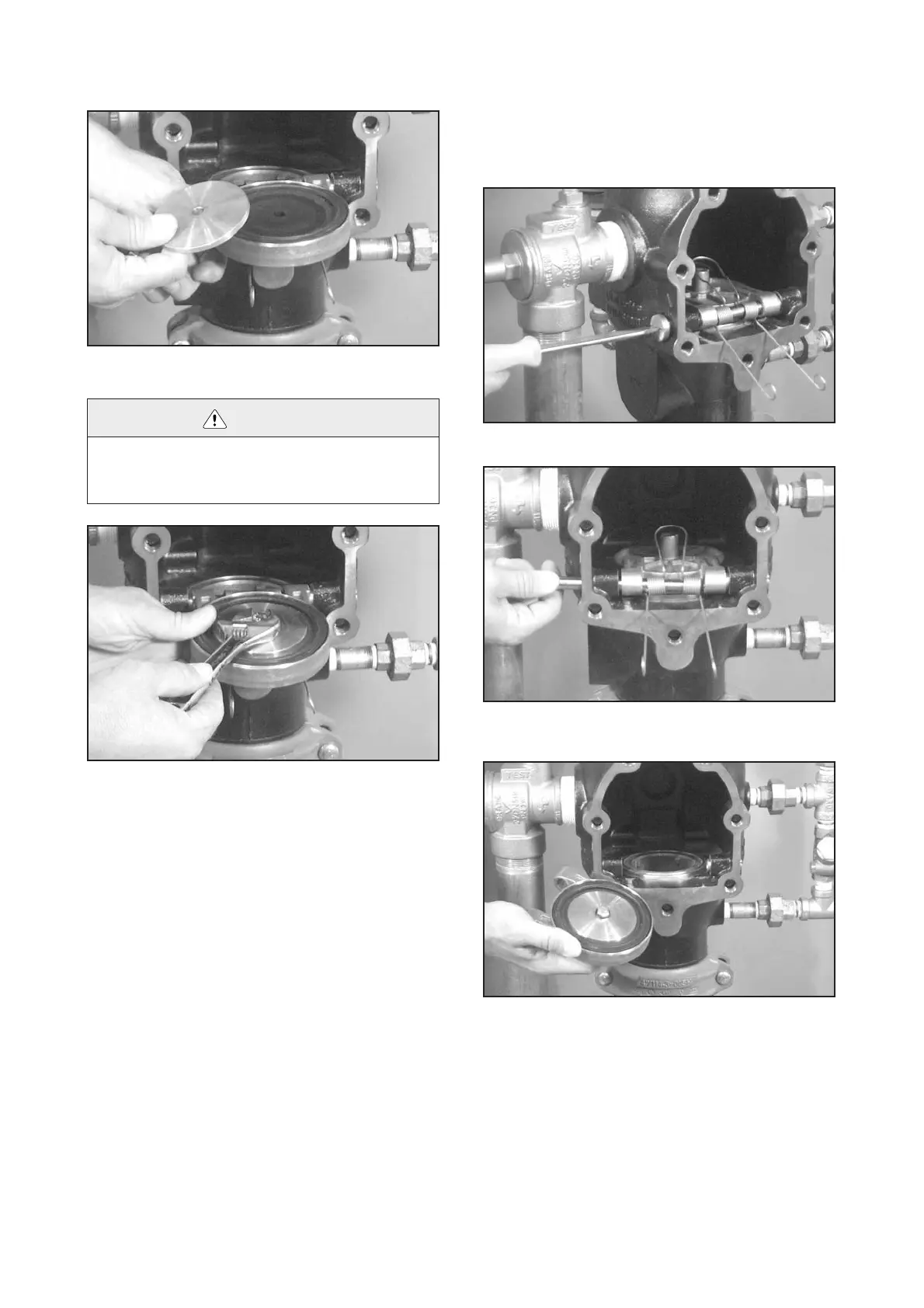
7. Place the seal-retaining ring onto the solid seal, as shown
above.
8. Install the seal assembly bolt/bolt seal through the seal-
retaining ring and the clapper. Tighten the seal assembly bolt/
bolt seal completely, and apply an additional ¹⁄₄ turn to ensure a
proper seal.
9. Replace the cover plate by following the “Installing Cover
Plate Gasket and Cover Plate” section, starting on page 14.
Removing and Replacing Clapper
Assembly
1. Perform steps 1 – 4 of the “Required Internal Inspection”
section, starting on page 10.
2. Remove one clapper shaft retaining bushing from the
valve body.
3. Remove the clapper shaft, as shown above. NOTE: As the
shaft is being removed, the clapper spring will drop out of posi-
tion. Keep the clapper spring for re-installation.
4. Remove the clapper from the valve body.
CAUTION
• Use only Victaulic-supplied replacement seal assembly bolt/ bolt seal when
reassembling the clapper.
Failure to follow this instruction could cause improper sealing, resulting in
valve leakage and/or property damage.

 Loading...


