Series 751 FireLock
®
European Alarm Check Valve Stations
4
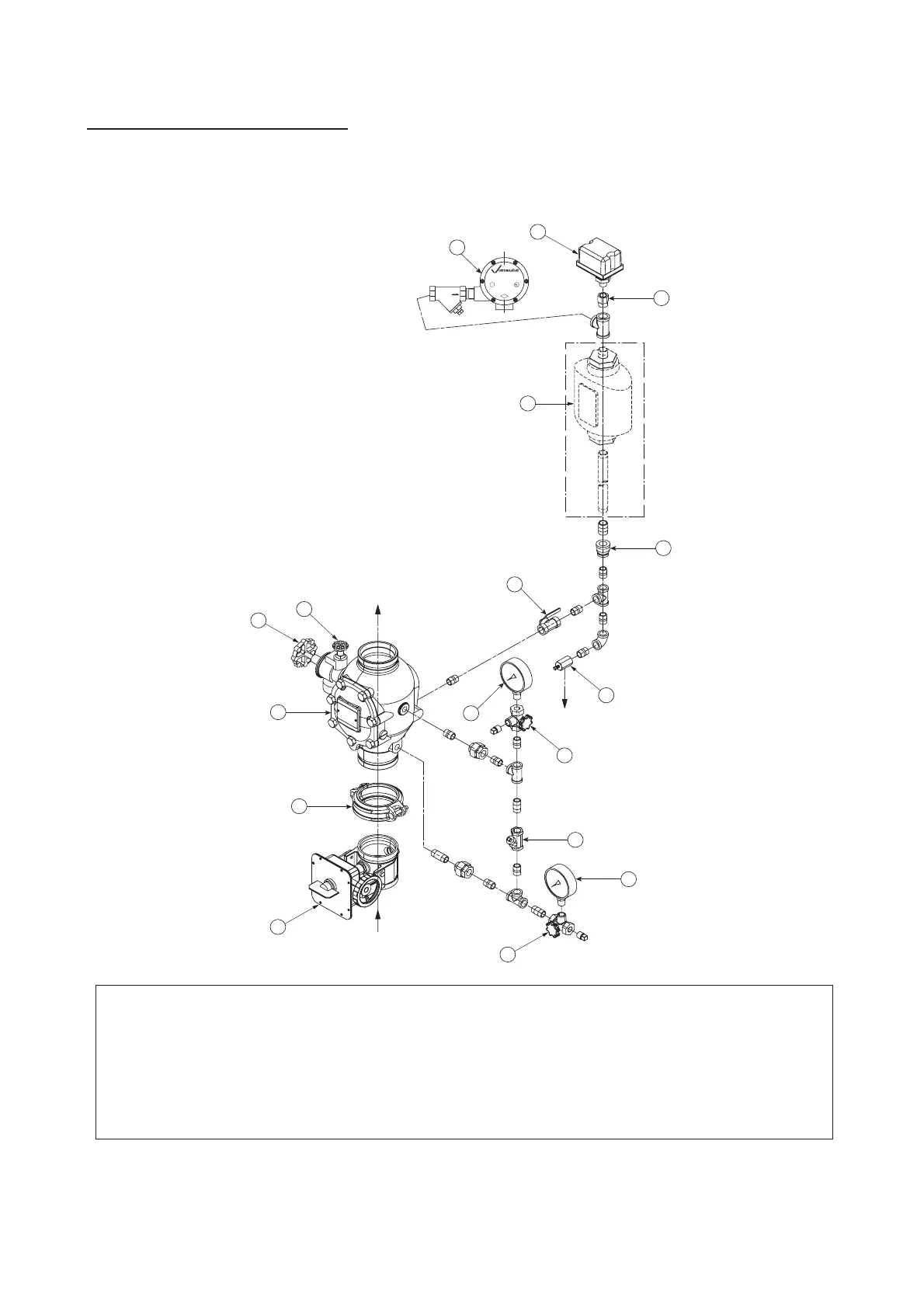
EXPLODED VIEW DRAWING – TRIM COMPONENTS
Series 751 FireLock™ European Alarm Check Valve Stations
(Optional Accessories Also Shown)
Grooved X Grooved
WATER MOTOR
ALARM
SERIES 760
150
F
³⁄₄
U
L
C
FM
LISTED
To Drain
Water
Supply
9
16
7
11
1
8
4
2
6
5
10
14
13
15
4
3
12
BILL OF MATERIALS
1 Series 751 FireLock European Alarm Check Valve 10 EPS-10 Alarm Pressure Switch
2 Style 005 FireLock Rigid Coupling 11 Alarm Line Ball Valve (Lockable - Normally Open)
3 Series 705W Butterfly Valve 12 Series 760 Water Motor Alarm
4 Gauge Valve with ³⁄₄-inch Strainer - 100 mesh (Optional)
5 Water Supply Pressure Gauge (0-25 Bar) 13 Series 752 Retard Chamber (Optional)
6 Swing Check Valve 14 System Main Drain Valve
7 Restricted Orifice/Alarm Line Drain 15 System Test Valve
8 Reducer 16 System Pressure Gauge (0-25 Bar)
9 Reducing Bushing
To
System
Normally
Open
(Lockable)
Optional
Retard
Chamber

 Loading...


