Series 751 FireLock
®
European Alarm Check Valve Stations
14
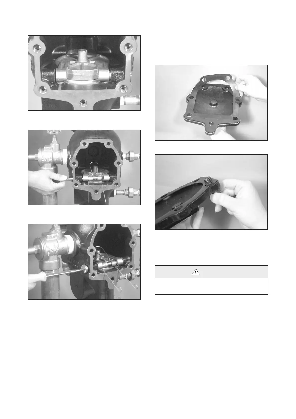
5. Place the new clapper assembly onto the valve body seat
ring so that the holes in the clapper arms align with the holes in
the valve body, as shown above.
6. Start the clapper shaft into the valve body, and install the
spring onto the clapper shaft. Make sure the loop is toward the
clapper, as shown above.
7. Install the clapper shaft retaining bushing into the valve
body.
8. Check the clapper for freedom of movement.
9. Replace the cover plate by following the “Installing Cover
Plate Gasket and Cover Plate” section, starting on this page.
Installing Cover Plate Gasket and Cover
Plate
1. Verify that the cover plate gasket is in good condition. If
the gasket is torn or worn, replace it with a new, Victaulic-sup-
plied gasket.
2. Align the cover plate gasket holes with the cover plate
holes.
3. Insert one cover bolt through the cover plate and cover
gasket to ease alignment.
4. Align the cover plate/cover plate gasket to the valve. Make
sure the spring arms are rotated to the installed position. Insert
all cover bolts and hand-tighten.
CAUTION
• DO NOT over-tighten the cover bolts.
Failure to follow this instruction could cause damage to the cover plate gas-
ket, resulting in valve leakage and/or property damage.

 Loading...


