AIR SUPPLY REQUIREMENTS
The required air pressure for Series 756 FireLock Dry Valves is 0.9 Bar
minimum, regardless of the system supply pressure. Air pressure must
be kept below 1.2 Bar.
Systems that require a Series 746-LPA Dry Accelerator should have air
pressure between 1.4 Bar and 1.6 Bar. NOTE: Air pressure should not
exceed 1.6 Bar. Refer to the requirements below.
Manufacturer’s Recommended Pressures – Series 746-LPA Dry
Accelerator:
Minimum Water Supply Pressure = 2.0 Bar
Minimum Air Supply Pressure = 1.4 Bar
Minimum Air Supply Pressure = 1.6 Bar
If multiple Series 756 FireLock Dry Valves are installed with a common
air supply, isolate the systems with a spring-loaded, soft-seated ball
ch
eck valve to ensure air integrity for each system. Good practice is to
include a ball valve for isolation and service of each individual system.
Set the air pressure to the required system air pressure. Air pressure
differing from the required system air pressure could reduce system
operation response time.
The engineer/system designer is responsible for sizing the compressor
so that the entire system is charged to the required air pressure within
30 minutes. DO NOT oversize the compressor to provide more airflow.
An oversized compressor will slow down or possibly prevent valve
operation.
If the compressor fills the system too fast, it may be necessary to
restrict the air supply. Restricting the air supply will ensure that air
being exhausted from an open sprinkler or manual release valve is not
replaced by the air supply system as fast as it is being exhausted.
COMPRESSOR SIZING
COMPRESSOR REQUIREMENTS
0
20
40
60
80
100
120
140
160
150 400 650 900 1150 1400 1650 1900 2150 2400 2650 2900 3150 3400 3650 3900 4150 4400 4650 4900 5150 540 5650 5900 6150 6400 66500
System Capacity (liters)
Required Flow Rate (lpm)
0,9-Bar System Air
1,4-Bar System Air
2,8-Bar System Air
3,8 Bar System Air
BASE OR RISER-MOUNTED AIR COMPRESSORS
For base or riser-mounted air compressors, the recommended air
pressure of 0.9 Bar is the “on” or “low” pressure setting for the com-
pressor. The “off” or “high” pressure setting should be 1.2 Bar.
When a base or riser-mounted air compressor supplies air to a Series
756 FireLock Dry Valve, it is not necessary to install the Victaulic Series
757 Regulated Air Maintenance Trim Assembly (AMTA). In this case,
the airline of the compressor connects to the trim at the fitting where
the Series 757 Regulated AMTA is normally installed (refer to the appli-
cable trim drawing). If the compressor is not equipped with a pressure
switch, the Series 757P Air Maintenance Trim Assembly with Pressure
Switch should be installed.
SHOP AIR OR TANK-MOUNTED AIR COMPRESSORS
In the event a compressor becomes inoperative, a properly sized tank-
mounted air compressor provides the greatest protection for systems.
Wh
en shop air or a tank-mounted air compressor is used, the Series
757 Regulated AMTA must be installed. The Series 757 Regulated
AMTA provides proper air regulation from the air reservoir to the
sprinkler system.
For tank-mounted air compressors, the recommended air pressure of
0.9 Bar should be used as the set point for the air regulator. The “on”
pressure of the compressor should be at least 0.3 Bar above the set
point of the air regulator.
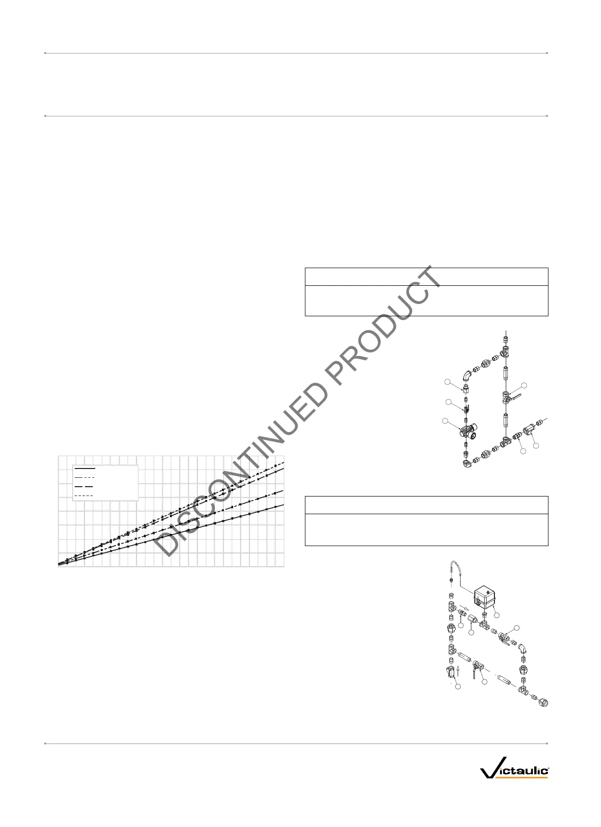
VICTAULIC SERIES 757 REGULATED AIR MAINTENANCE TRIM
ASSEMBLY (AMTA)
NOTICE
Victaulic recommends a maximum of two Series 756 FireLock
Dry Valves per Series 757 Regulated AMTA.
•
1
6
5
4
2
3
Bill of Materials
1 3.2-mm Restrictor
2 Slow Fill Ball Valve (Normally Open)
3 Air Regulator
4 Strainer (100 Mesh)
5 Spring-Loaded, Soft-Seated
Ball Check Valve
6 Fast Fill Ball Valve (Normally Closed)
VICTAULIC SERIES 757P AIR MAINTENANCE TRIM ASSEMBLY
(AMTA) WITH PRESSURE SWITCH
NOTICE
Victaulic recommends a maximum of two Series 756 FireLock
Dry Valves per Series 757P AMTA with Pressure Switch.
•
3
4
5
2
6
1
Bill of Materials
1 3.2-mm Restrictor
2 Pressure Switch
3 Slow Fill Ball Valve (Normally Open)
4 Fast Fill Ball Valve (Normally Closed)
5 Strainer (100 Mesh)
6 Spring-Loaded, Soft-Seated
Ball Check Valve
I-756LPA.VDS_8
FireLock
®
European Dry Valve Stations
SERIES 756
WITH SERIES 776 LOW-PRESSURE ACTUATOR
I-756LPA.VDS
INSTALLATION, MAINTENANCE, AND TESTING MANUAL
www.victaulic.com
VICTAULIC IS A REGISTERED TRADEMARK OF VICTAULIC COMPANY. © 2006 VICTAULIC COMPANY. ALL RIGHTS RESERVED. PRINTED IN THE USA.
REV_B
 Loading...


