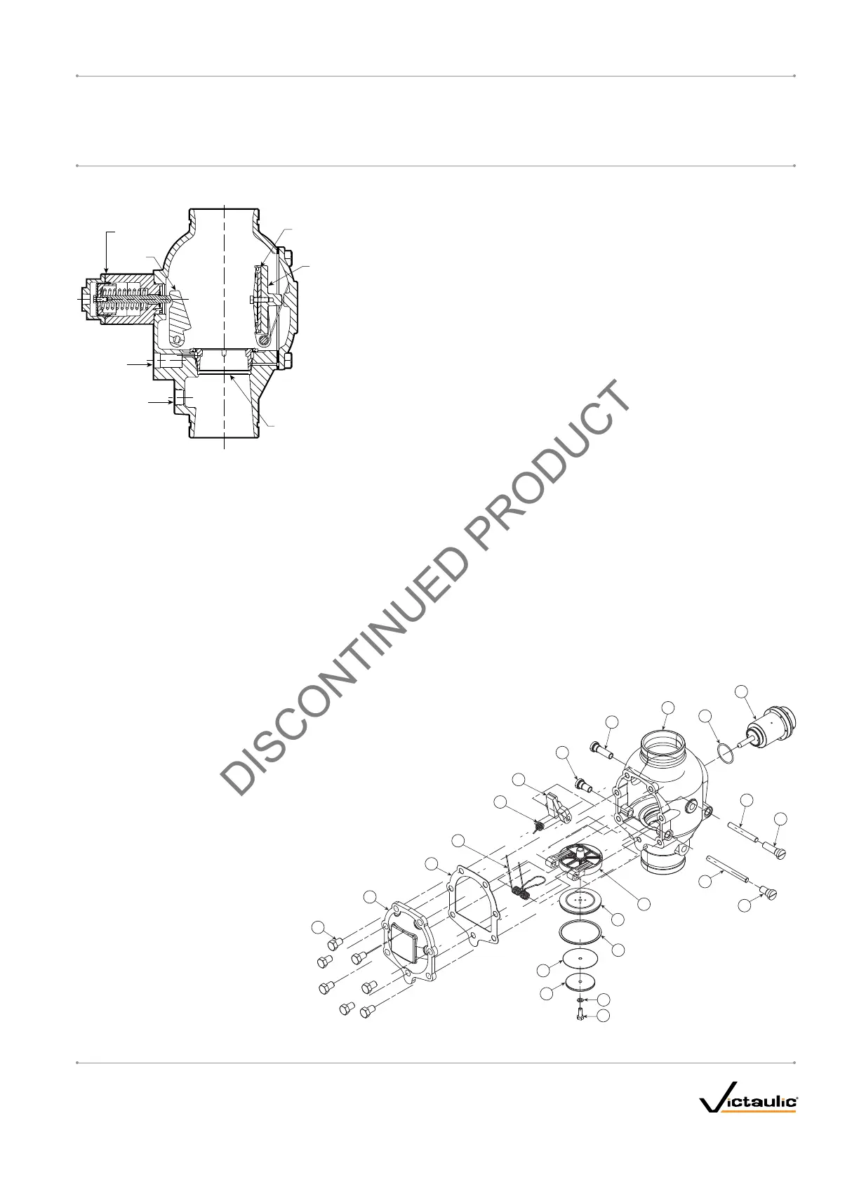
EXPLODED VIEW DRAWING – INTERNAL VALVE COMPONENTS
Clapper
Seal
Latch
Piston
Assembly
Alarm
Outlet
Alarm
Test
Seat
Exaggerated for Clarity
Bill of Materials
1 Valve Body 11 Clapper Shaft Retaining Bushing
2 Clapper 12 Latch Shaft
3 Clapper Seal 13 Latch Shaft Retaining Bushing
4 Seal Ring 14 Piston O-ring
5 Seal Washer 15 Piston
6 Seal-Retaining Ring 16 Cover Plate Gasket
7 Bolt Seal 17 Cover Plate
8 Seal Assembly Bolt 18 Cover Plate Bolt
9 Clapper Spring 19 Latch
10 Clapper Shaft 20 Latch Spring
1
2
12
13
13
9
20
19
6
5
4
3
10
11
14
11
15
8
7
16
17
18
I-756LPA.VDS_5
FireLock
®
European Dry Valve Stations
SERIES 756
WITH SERIES 776 LOW-PRESSURE ACTUATOR
I-756LPA.VDSINSTALLATION, MAINTENANCE, AND TESTING MANUAL
www.victaulic.com
VICTAULIC IS A REGISTERED TRADEMARK OF VICTAULIC COMPANY. © 2006 VICTAULIC COMPANY. ALL RIGHTS RESERVED. PRINTED IN THE USA.
REV_B
 Loading...


