REQUIRED OPERATIONAL (TRIP) TESTS
PARTIAL OPERATIONAL (TRIP) TEST
WARNING
The building owner or their representative is responsible for
maintaining the fire protection system in proper operating
condition.
To ensure proper system operation, valves must be inspected
in accordance with current national standards or in accordance
with the requirements of the local authority having jurisdiction
(whichever is more stringent). Always refer to the instructions
in this manual for additional inspection and testing require-
ments.
The frequency of inspections must be increased in the
presence of contaminated water supplies, corrosive/scaling
water supplies, and corrosive atmospheres.
Depressurize and drain the piping system before attempting to
install, remove, adjust, or maintain any Victaulic products.
Failure to follow these instructions could cause system failure,
resulting in death, serious personal injury, and property damage.
•
•
•
•
Partial operational (trip) tests are required at least once a year to
confirm proper valve operation; however, this test does not confirm
fu
ll system operation. Victaulic recommends performing the partial
operational (trip) test annually (at minimum). NOTE: The frequency of
the partial operational (trip) test must be increased in the presence
of contaminated water supplies, corrosive/scaling water supplies, and
corrosive atmospheres. In addition, the authority having jurisdiction in
the area may require partial operational (trip) tests on a more frequent
basis. Verify these requirements by contacting the authority having
jurisdiction in the affected area.
1. Notify the authority having jurisdiction, remote station alarm
monitors, and those in the affected area that the partial operational
(trip) test will be performed.
2. Record the system air pressure (7) and water supply pressure (5).
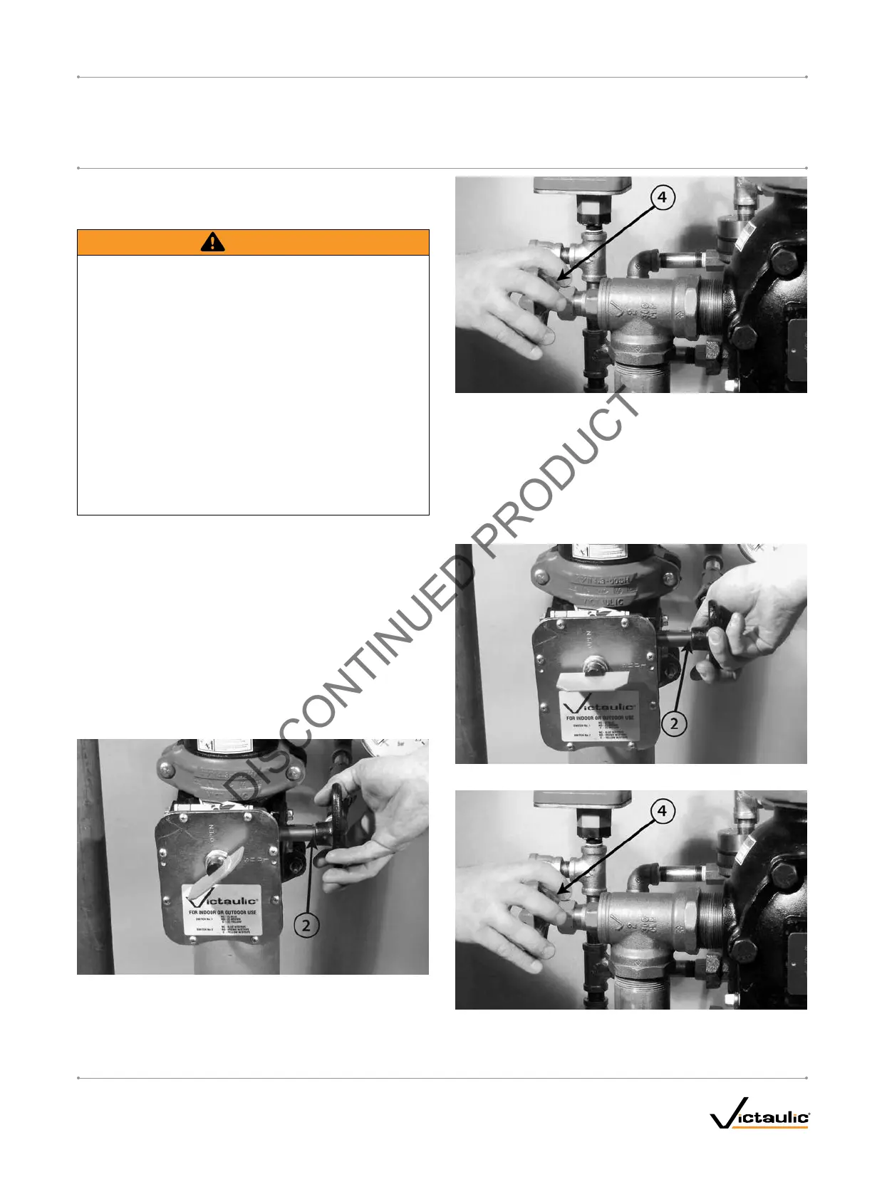
3. Partially close the water supply main control valve (2).
4. Open the remote system test valve (inspector's test connection)
or the system main drain valve (4) to simulate an open sprinkler.
NOTE: The system main drain valve (4) is shown above.
5. Record the system air pressure (7) when the valve operates, along
with any other information required by the authority having juris-
diction.
6. Confirm that the piston charge line's pressure drops to zero and
that water is flowing through the auto drain (12) to the drip cup
(15).
7. Close the water supply main control valve (2) fully.
8. Close the remote system test valve (inspector's test connection)
or the system main drain valve (4). NOTE: The system main drain
valve (4) is shown above.
I-756LPA.VDS_21
FireLock
®
European Dry Valve Stations
SERIES 756
WITH SERIES 776 LOW-PRESSURE ACTUATOR
I-756LPA.VDSINSTALLATION, MAINTENANCE, AND TESTING MANUAL
www.victaulic.com
VICTAULIC IS A REGISTERED TRADEMARK OF VICTAULIC COMPANY. © 2006 VICTAULIC COMPANY. ALL RIGHTS RESERVED. PRINTED IN THE USA.
REV_B
 Loading...


