INTRODUCTION
The following instructions are a guide for proper installation of Victaulic Series 756 FireLock Dry Valves. These instructions involve pipe that is
properly prepared and grooved in accordance with Victaulic specifications.
NOTICE
Drawings and/or pictures in this manual may be exaggerated for clarity.
This product and this installation, maintenance, and testing manual contain trademarks, copyrights, and/or patented features that are the
exclusive property of Victaulic.
•
•
TRIM
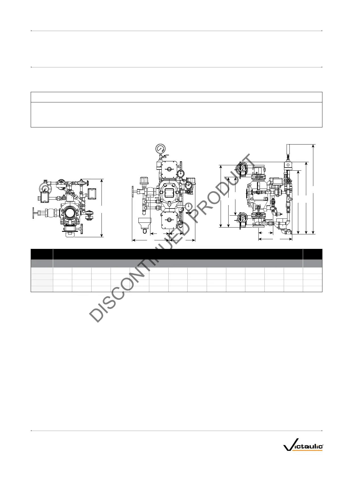
DIMENSIONS
Size Dimensions – centimeters
Approx.
We
ight Ea.
A* A1 A2
B B1 B2 C D E F G H I kg
DN80 32.03 59.00 42.24 70.00 71.70 92.50 34.26 55.90 30.17 22.80 14.04 16.65 12.88 46.0
DN100 38.18 63.12 50.66 64.63 73.37 92.00 34.10 58.80 37.72 26.28 14.79 19.30 13.82 67.0
DN150 40.64 71.99 56.32 67.02 78.19 93.00 38.26 65.44 38.68 25.38 18.17 20.27 15.38 80.0
DN200 44.45 86.32 65.38 68.59 86.17 95.00 37.53 64.39 42.16 28.71 20.86 23.75 18.67 116.0
* The “A” dimension is the measurement from the top of the valve body to the bottom of the valve body (takeout dimension).
NOTE: the upper butterfly valve is optional.
I-756LPA.VDS_3
FireLock
®
European Dry Valve Stations
SERIES 756
WITH SERIES 776 LOW-PRESSURE ACTUATOR
I-756LPA.VDSINSTALLATION, MAINTENANCE, AND TESTING MANUAL
www.victaulic.com
VICTAULIC IS A REGISTERED TRADEMARK OF VICTAULIC COMPANY. © 2006 VICTAULIC COMPANY. ALL RIGHTS RESERVED. PRINTED IN THE USA.
REV_B
 Loading...


