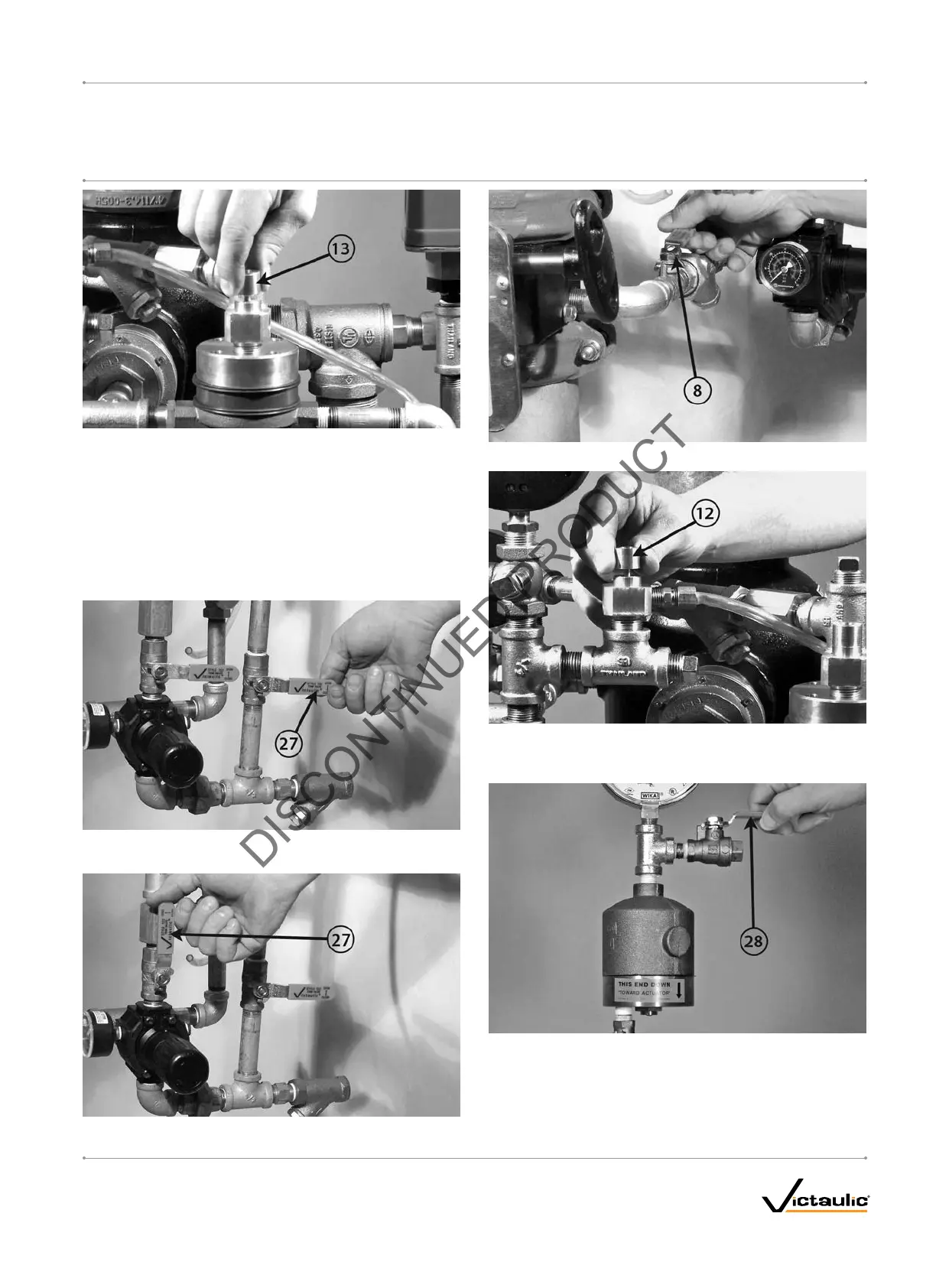
11. When the system reaches approximately 0.7 Bar, pull up on the
Auto Vent Sleeve of the Series 776 Low-Pressure Actuator (13).
NOTE: The Auto Vent Screw should seal and remain in the set
("UP") position.
11a. Confirm that no water is being exhausted from the Auto Vent
of the Series 776 Low-Pressure Actuator (13). If water is
being exhausted from the Auto Vent of the Series 776 Low-
Pressure Actuator, continue to run air through the system. If
a Series 746-LPA Dry Accelerator (28) is installed, make sure
the accelerator is not flooded.
12. When system air pressure is established, close the fast-fill ball
valve on the AMTA (27).
13. Open the slow-fill ball valve on the AMTA (27).
14. Open the piston-charge-line ball valve (8).
15. Pull up on the Auto Drain Sleeve (12) until the screw is in the set
("UP") position. Verify that there is pressure on the gauge to the
piston charge line (11).
16. If a Series 746-LPA Dry Accelerator (28) is installed, open the ¼-
turn vent ball valve.
I-756LPA.VDS_13
FireLock
®
European Dry Valve Stations
SERIES 756
WITH SERIES 776 LOW-PRESSURE ACTUATOR
I-756LPA.VDSINSTALLATION, MAINTENANCE, AND TESTING MANUAL
www.victaulic.com
VICTAULIC IS A REGISTERED TRADEMARK OF VICTAULIC COMPANY. © 2006 VICTAULIC COMPANY. ALL RIGHTS RESERVED. PRINTED IN THE USA.
REV_B
 Loading...