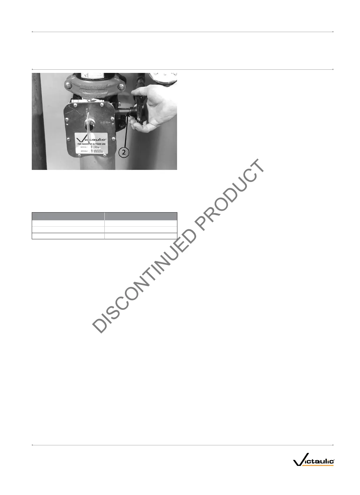
24. Open the water supply main control valve (2) fully.
25. Record the system air pressure (7) and the water supply pressure
(5).
26. Confirm that all valves are in their normal operating positions (refer
to the table below).
Valve Normal Operating Position
Piston-Charge-Line Ball Valve Open (Lockable)
Alarm Line Ball Valve Open (Lockable)
Alarm Test Ball Valve Closed
27. Notify the authority having jurisdiction, remote station alarm moni-
tors, and those in the affected area that the system is in service.
ON A WEEKLY BASIS, WHEN THE VALVE IS RESET AFTER AN
OPERATIONAL TEST (OR AFTER ANY SYSTEM OPERATION): The
low-body drain valve and any low-point drain valves should be partially
opened and then closed to drain water that might be present in the
riser. Continue this procedure until all water is released. NOTE: The
optional Series 75D Water Column Kit can be installed to automate this
step.
I-756LPA.VDS_15
FireLock
®
European Dry Valve Stations
SERIES 756
WITH SERIES 776 LOW-PRESSURE ACTUATOR
I-756LPA.VDSINSTALLATION, MAINTENANCE, AND TESTING MANUAL
www.victaulic.com
VICTAULIC IS A REGISTERED TRADEMARK OF VICTAULIC COMPANY. © 2006 VICTAULIC COMPANY. ALL RIGHTS RESERVED. PRINTED IN THE USA.
REV_B
 Loading...