18
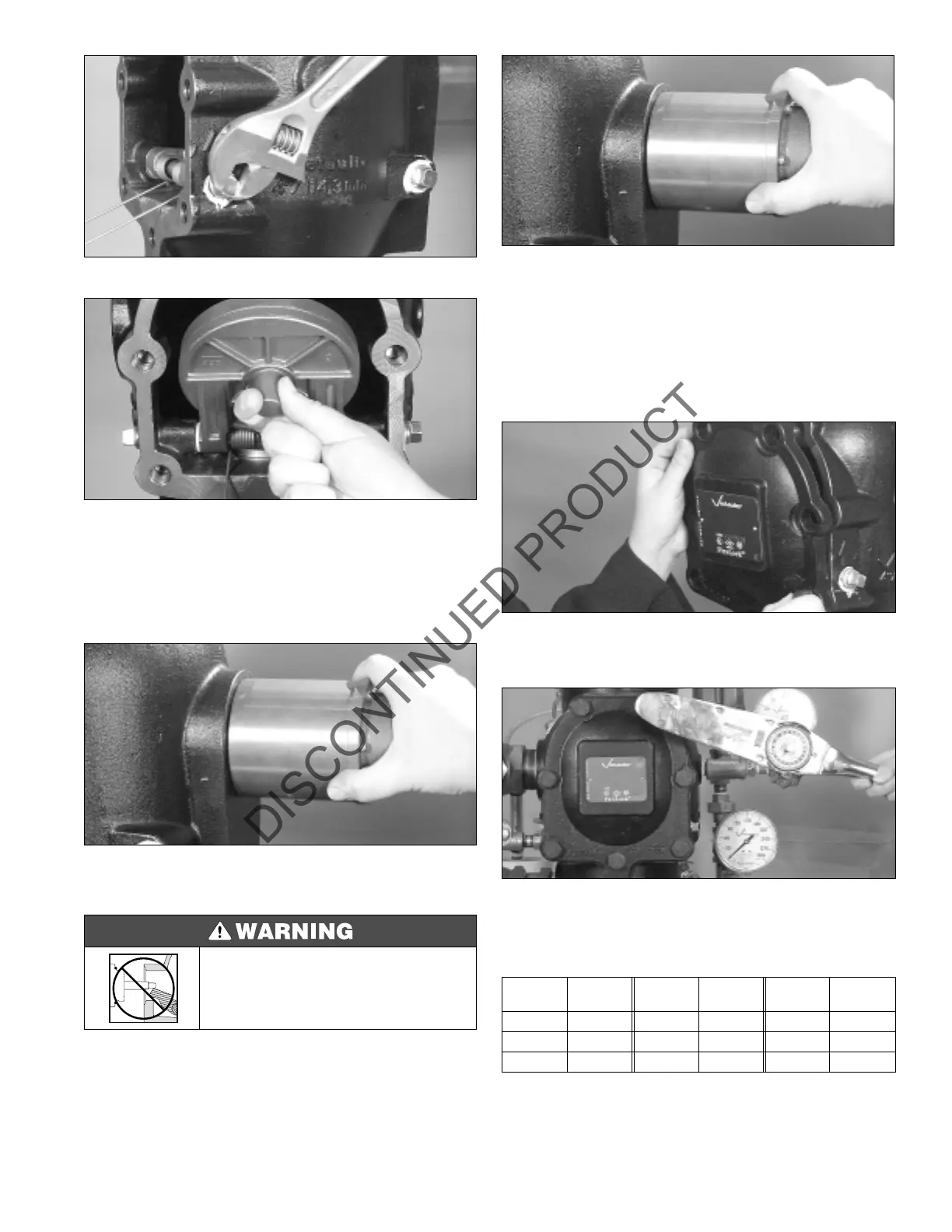
4. Screw the shaft retaining plugs back into the body.
5. Confirm the free movement of the clapper prior to
assembling the valve.
REMOVING THE ACTUATOR PISTON
1. Disconnect the trim from the piston.
2. Unscrew the piston from the valve body.
3. Repair or replace the piston assembly.
4. Screw the piston into the valve body.
5. Attach the trim as per the trim drawings.
INSTALLING THE COVER PLATE
1. Verify that the cover gasket is in good condition; if not,
replace the gasket. Align the cover plate gasket with the
holes on the cover plate. Insert one bolt through the cover
plate and cover gasket.
2. Align the cover plate and cover gasket to the valve.
Ensure that the spring arms are now rotated to their
installed position. Insert the bolts by hand.
3. Tighten all bolts using an alternate and even pattern.
Tighten the bolts to the proper torque per the chart below.
Do not over-tighten or under-tighten these bolts.
Recommended Cover Bolt Torque
Place the system back in service by following the “Placing
the System in Service” section on page 8.
• Make sure you reassemble and install the piston correctly
according to the instructions contained in this manual.
Failure to follow these instructions could result in serious
personal injury, valve malfunctioning, and/or property dam-
age.
Size
(Inches)
Torque
(Ft. Lbs.)
Size
(Inches)
Torque
(Ft. Lbs.)
Size
(Inches)
Torque
(Ft. Lbs.)
1¹⁄₂ 30 76,1 mm 60 6 115
2 30 3 60 165,1 mm 115
2¹⁄₂ 60 4 100 8 100
 Loading...


