7
INSTALLATION
For proper operation and approval, you must install the
valve in accordance with the trim diagrams for the Series
758 Preaction Valve. Victaulic provides specific trim draw-
ings for all release installations.
NOTE:
The Series 753-A Dry Actuator
CANNOT
be used
on double-interlock pneumatic/electric or pneumatic/pneu-
matic setups. These systems require a 758-LPA system.
The Series 758 Preaction Valve must
NOT
be located in an
area that is subject to freezing temperatures. In addition,
the valve must
NOT
be located in an area where physical
damage may occur. It is the owner’s responsibility to con-
firm material compatibility of the Series 758 Preaction
Valve, trim, and associated accessories when a corrosive
atmosphere or contaminated water is present.
Air or nitrogen supply to the Preaction piping system must
be clean, dry, and oil free. Automatic air supplies must be
regulated, restricted, and continuous. Victaulic recom-
mends the installation of an air maintenance device on any
system with an automatic air supply.
When used with a water motor alarm, configure the valve
with an uninterrupted, low-pressure alarm mounted to the
valve’s piston.
NOTE:
You do not need to add a check valve to the riser
above the preaction valve. The clapper is not subject to
water columning and, in addition, the preaction valve itself
acts as a spring-loaded check valve after it trips.
Prior to installing the valve, flush the water supply piping
thoroughly in order to ensure that no foreign objects are
present.
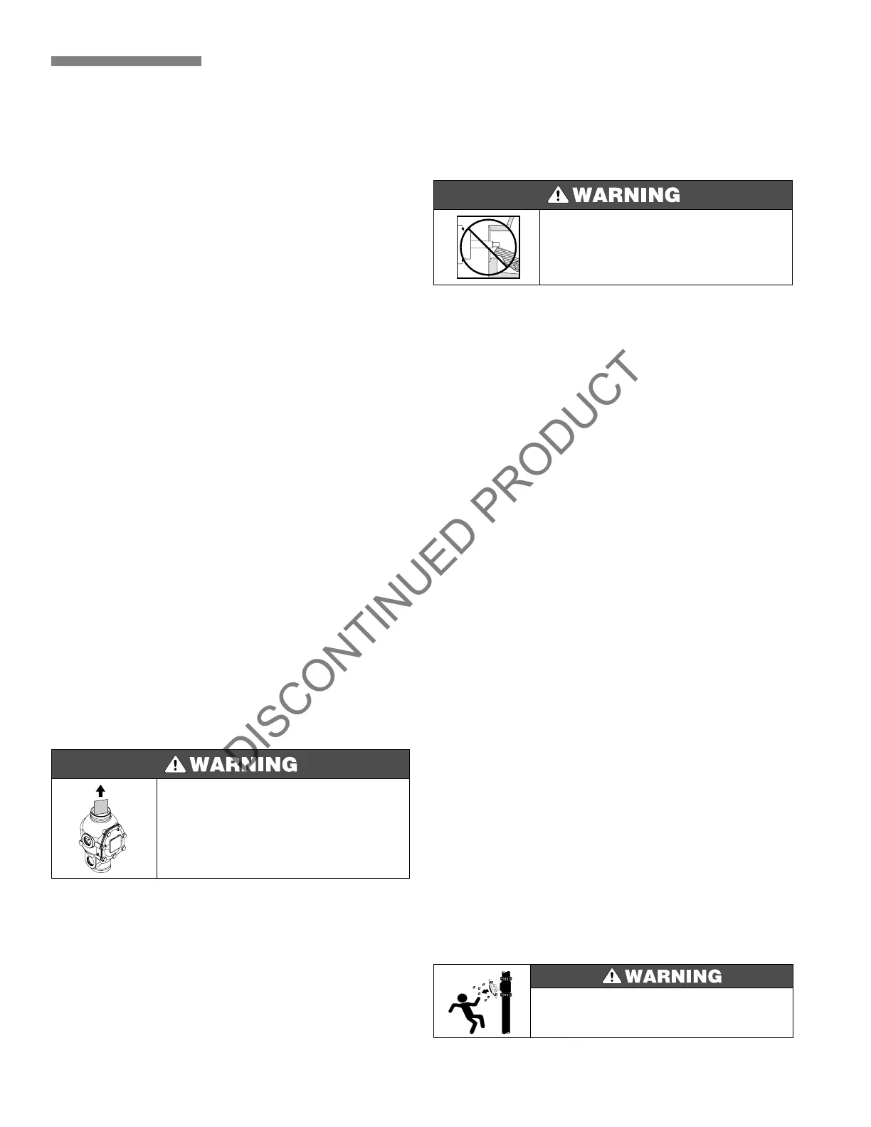
Install the Series 758 Preaction Valve in the vertical posi-
tion with the arrow on the body pointing upward.
1.
Confirm that all required drawings and data for the
installation of the valve are available.
2.
Remove all plastic caps from the valve.
3.
For valves 3" (88,9 mm) or smaller, it is necessary to
remove the piston assembly when trimming the valve.
3a.
Unscrew the piston from the valve’s body.
3b.
Note the position of the o-ring. This o-ring must be in
the same position when you reassemble the piston.
3c.
Install the trim to the back of the valve.
3d.
Reassemble the piston, making sure that the o-ring is
positioned properly and that the piston rod and the latch
engage properly. It may be necessary to rotate the latch
inward (toward the valve body’s center) to ensure proper
alignment.
3e.
Tighten the piston until you achieve metal to metal
contact with the valve body.
4.
Apply a small amount of pipe joint compound or Teflon*
pipe tape to the external threads of all threaded pipe con-
nections. Be careful not to get any tape, compound, or
other foreign substances into the valve or the inside of any
nipples or valve openings.
5.
Make sure that the trim drawing matches the system’s
requirements. Install the Victaulic Series 758 Actuated
Valve in accordance with the applicable trim drawings.
6.
Provide an uninterrupted source of water from
upstream of the main control valve to supply pressure to
the piston charge line before opening the main control
valve.
IMPORTANT SETTINGS
Pneumatic Release Systems
1.
Supply a minimum air pressure, determined from the
chart on page 6, for pneumatic release systems.
2.
Set the air supervisory switch to activate at 5 psi
(34 kPa) below the minimum air pressure required.
3.
Wire the air supervisory switch to activate a low pres-
sure alarm signal. A high pressure alarm may also be
required by the authority having jurisdiction.
Electric Release Systems
1. Apply the minimum amount of air for proper supervi-
sion, depending on the type of supervisory switch you are
using.
Alarm Pressure Switch
1. Set the alarm pressure switch to activate on a pressure
rise of 4 - 8 psi (25 - 55 kPa). Wire the alarm pressure switch
to activate a water flow alarm.
Air Supply Design
1. Size the air supply system to establish the required air
pressure in the system within 30 minutes. The air supply
must be regulated, restricted, and maintained automati-
cally.
• Valves are shipped with a cardboard spacer holding the
clapper shut. This spacer MUST be removed BEFORE in-
stallation of the valve.
Failure to follow this instruction could result in serious per-
sonal injury, property damage, valve leakage, and/or valve
failure.
• Make sure you reassemble and install the piston correctly
according to the instructions contained in this manual.
Failure to follow these instructions could result in serious
personal injury, valve malfunctioning, and/or property dam-
age.
• Properly size and build the air supply system.
Failure to follow this instruction could result in serious per-
sonal injury, property damage, and/or valve leakage.
*Teflon is a registered trademark of I.E. Dupont de Nemours.
 Loading...


