8
2. Regulate the air pressure to the proper system air pres-
sure. Air pressure differing from the required system air
pressure could affect the operation of the system adversely.
3. Restrict the air supply in order to ensure that air being
exhausted from an open head or manual release valve is
not replaced by the air supply system as fast as it is being
exhausted.
4. It is recommended practice that an inspector’s test con-
nection be provided on the release system. This inspector’s
test connection should be equipped with a ball valve (nor-
mally locked closed), which can be opened in order to sim-
ulate the actuation of a release device. Locate the test
connection at the highest, most hydraulically demanding
location in the release system. The test connection should
terminate with an orifice equal to the smallest orifice in the
releasing system. The inspectors test connection can be
used in order to confirm that the air or water supply sys-
tems are not supplying pressure at a rate faster than the
releasing device can exhaust pressure.
PLACING THE SYSTEM
IN SERVICE
When the preaction system is ready to be placed in ser-
vice, verify that all equipment is heated and protected
properly from freezing temperatures and physical damage.
1. Open the system main drain valve located above the
clapper. Confirm that the system is drained.
2. Close the system main drain valve.
3. Confirm that the system drains are shut and that the
system is free of leaks.
4. For electric release systems: Open the piston
charge line ball valve. Make sure that no water flows from
the solenoid.
4a. Remove the red protective cap from the Series 749
Auto Drain. Pull up on the auto drain set screw until the
auto drain is set (approximately 10 psi/69 kPa). Replace the
protective cap on the auto drain.
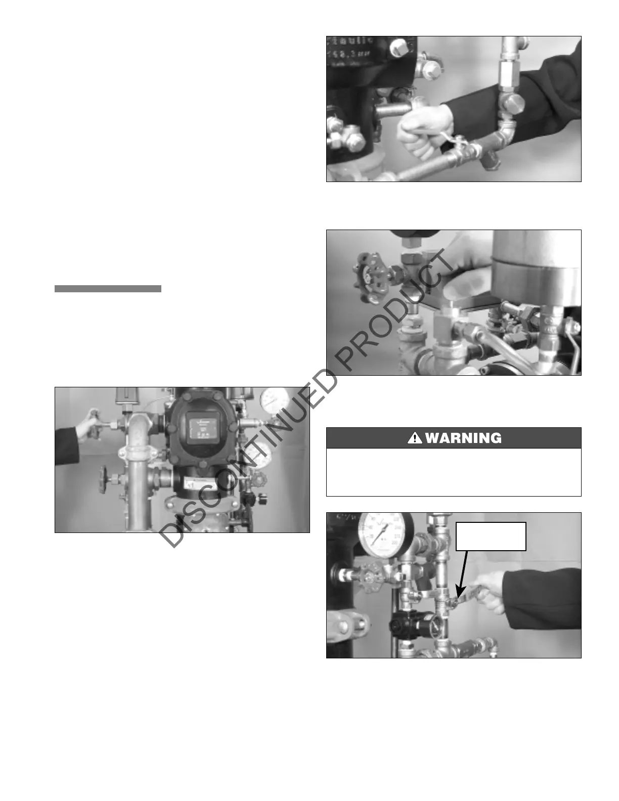
5. For pneumatic systems: Open the fast fill ball valve
on the air maintenance device. Fill the system to the
appropriate air pressure for the typical water supply pres-
sure in the area.
• Make sure you always replace the protective cap over the auto drain set screw of the
Series 749 to avoid accidental contact. Hitting the set screw will cause the valve to
trip.
Failure to follow this instruction could result in serious personal injury, and/or property
damage.
FAST FILL
BALL VALVE
 Loading...


