Digital multimeter
18 / 25
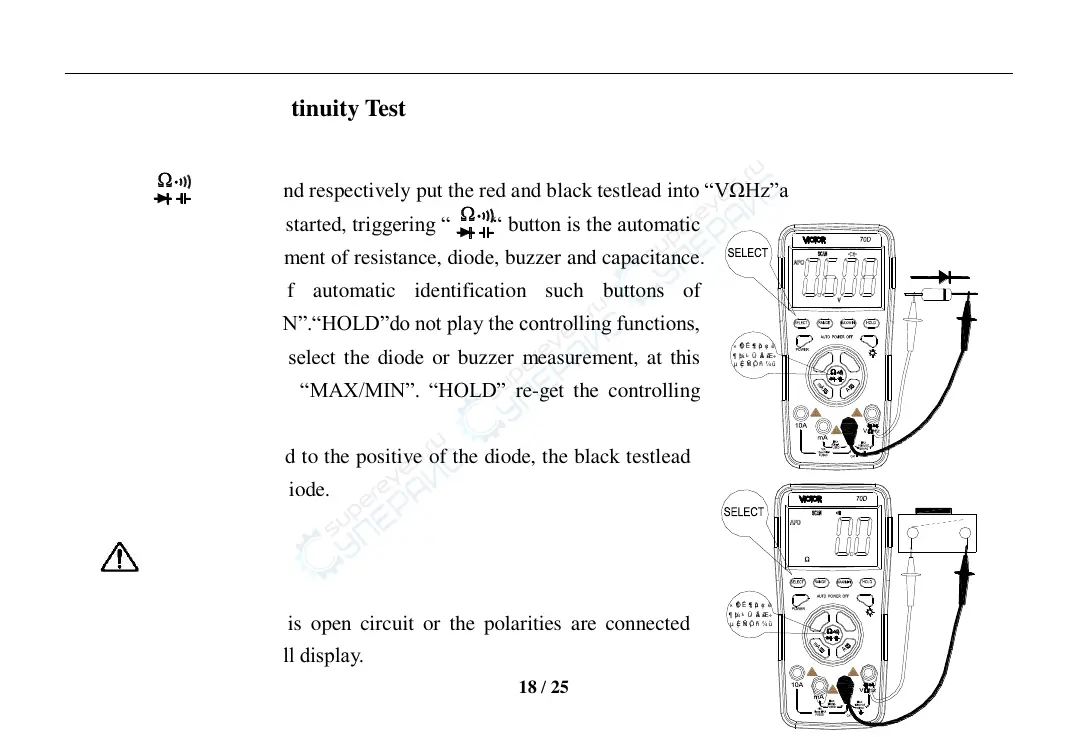
XIII.Diode and Continuity Test
1. Press “ ” button and respectively put the red and black testlead into “VΩHz”and“COM” terminal.
2. After the instrument is started, triggering “ “ button is the automatic
identification measurement of resistance, diode, buzzer and capacitance.
Under the mode of automatic identification such buttons of
“RANGE”.“MAX/MIN”.“HOLD”do not play the controlling functions,
trigger “SELECT” to select the diode or buzzer measurement, at this
time such buttons as “MAX/MIN”. “HOLD” re-get the controlling
functions.
3. Connect the red testlead to the positive of the diode, the black testlead
to the negative of the diode.
Caution:
a)In case the diode is open circuit or the polarities are connected
reversely, “OL” will display.
× Ô¶ ¯Ê ¶± ðµ ç× è
¶ þ¼ «¹ Ü · äà ùÆ÷
AC/
EF
DC/
Hz
µ çÈ ÝÑ ¡Ô ñ° ´¼ü
µ çÈ ÝÑ ¡Ô ñ° ´¼ü
Hz
DC/
EF
AC/
¶ þ¼ «¹ Ü · äà ùÆ÷
× Ô¶ ¯Ê ¶± ðµ ç× è
 Loading...