Pag. 6 MNVCPTH300_1541_EN
Connectors and connections
The installation must be carried out only by qualified technical staff: an improper connection of the peripheral
units may cause the keyboard to be isolated from the rest of the system.
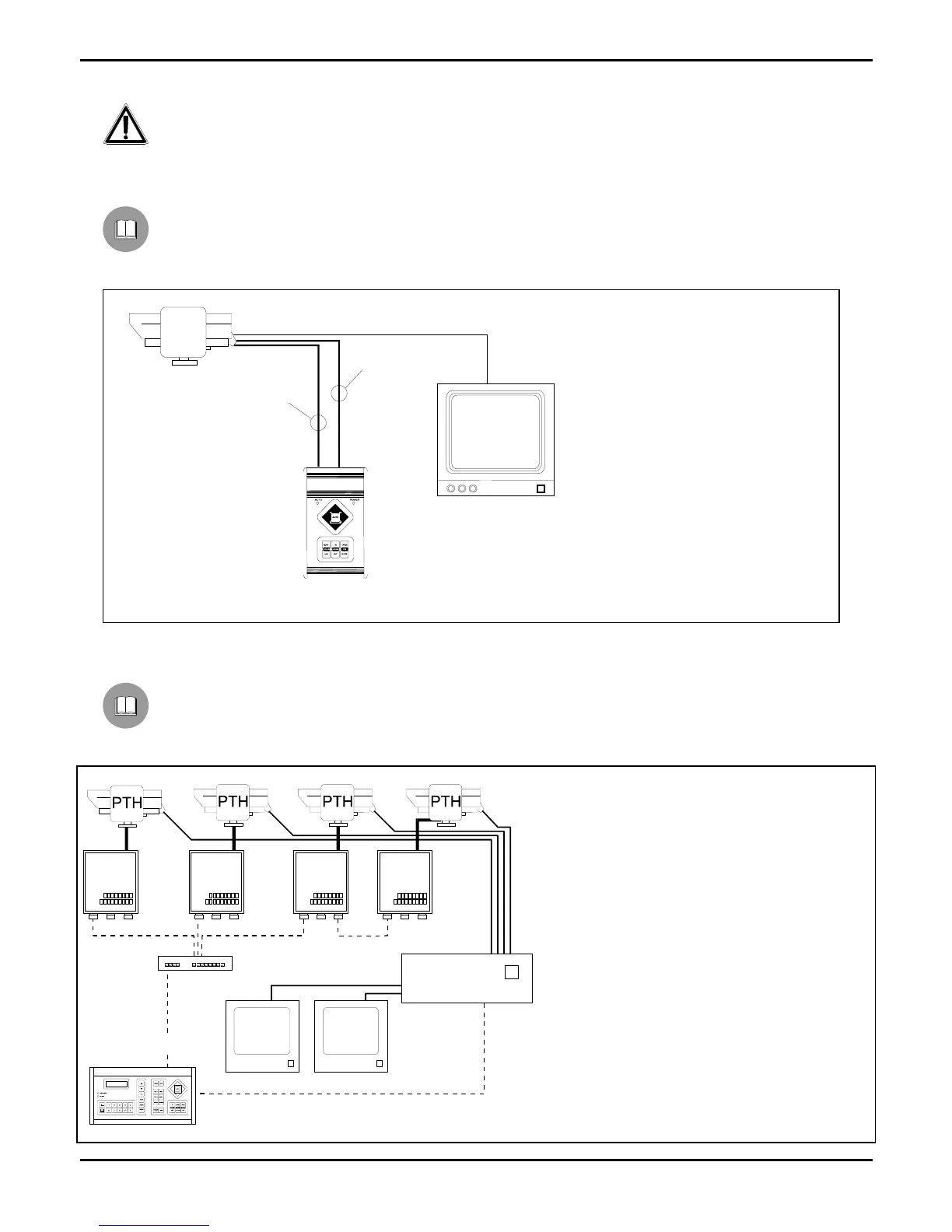
Installation example
Installation controlled by one operator with one monitor: the operator controls one pan & tilt motor and the
following telecamera functions FOCUS, ZOOM, DIAPHRAGM (IRIS):
MATERIAL USED
Control keyboard:
1 CBZ control keyboard
Video handling:
1 monitor
Telemetry handling:
1 PTH310 / PTH311
pan & tilt motor
1 motorized zoom lens
Installation example
One operator with more monitors, who controls a series of pan & tilt motors in mixed configuration (star and
cascade connection)
MATERIAL USED
Control keyboard:
1 DCS2 control keyboard
Video handling:
1 SW164OSM video switcher
2 monitors
4 telecameras
Telemetry handling:
1 DCMX serial data multiplexer
4 DTRX3 receivers
4 PTH310 / PTH311
pan & tilt motors
DTRX3
DTRX3
DTRX3
DTRX3
DCS2
SW164OSM
DCMX
CBZ
7 wires-cable for the
control of the P&T
head
P&T
6 wires-cable for
the control of the
lense
 Loading...