Pag. 7 MNVCPTH300_1541_EN
Cables
Different types of stroke have been used in the previous examples, in order to indicate cables with different
functions:
video cable:
RG 59 coaxial cable or equivalent cable
multipolar cable:
each control function of the positioning device is activated /deactivated by a relay positioned inside the receiver.
Fix the final numbers of wires according to the following directions:
7 wires for the motion of the positioning device: right, left, up, down, autopan, common, ground
6 wires for the control of polarity reversal lenses (zoom, focus, iris)
4 wires for the control of common wire lenses (zoom, focus, iris)
2 wires for the auxiliary device
Note: We recommend the use of different multipolar cables for high tension and low tension functions.
Minimum section area recommended: 0.56 mm.² (AWG 20) for high tension wires (positioning device)
0.34 mm.² (AWG 22) for low tension wires (lens, auxiliary device)
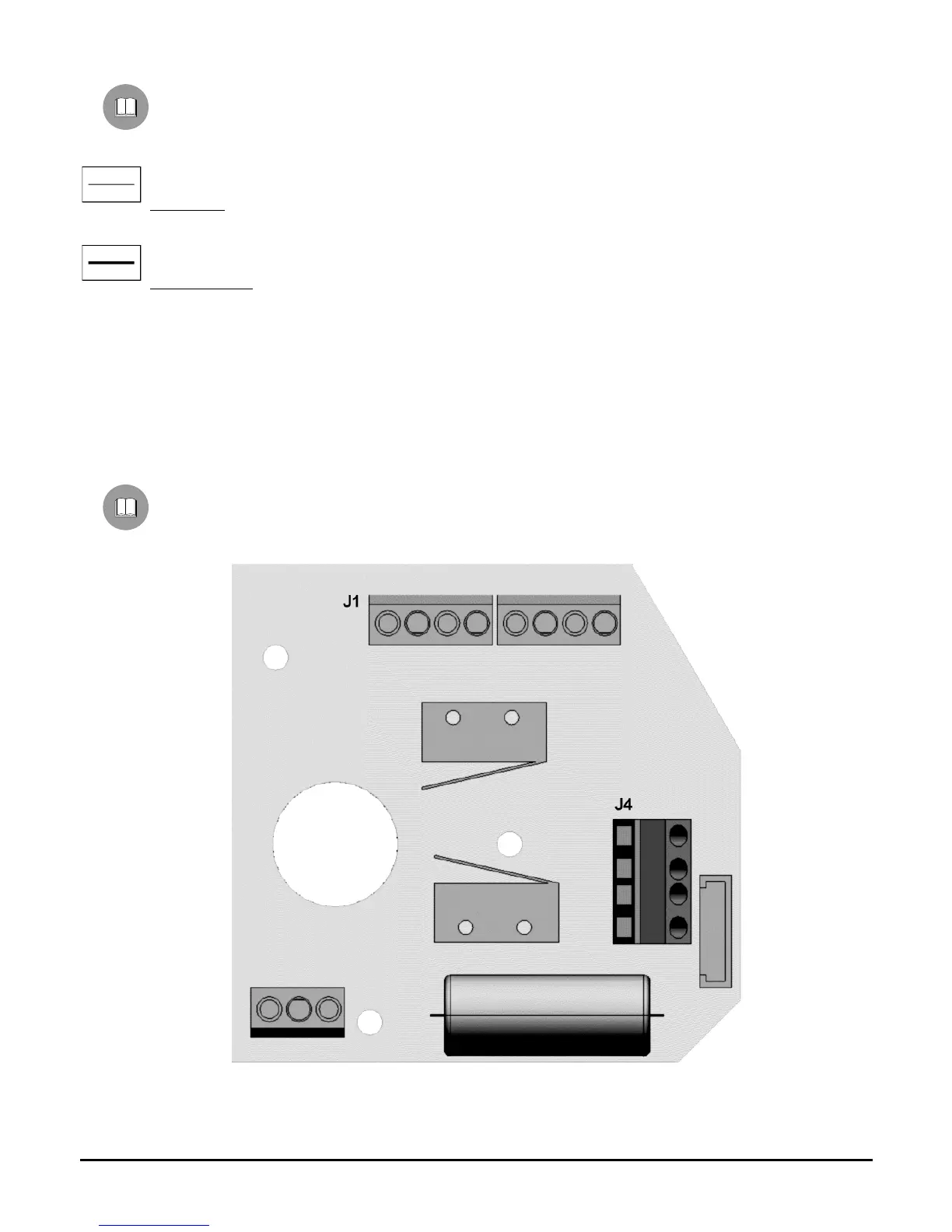
Pan & tilt connection to control units
In the following drawing, identify the terminal block J1 in the lower printed circuit for the pan & tilt connection to
the control units:
 Loading...