66250203 - V4.4 - 15/05/22
- 12 -
4000 Series Vandal Resistant Range
Art.4212 - Installation instructions
DEVICE
Device par. menu Parameter Name Programming method Permission Default value
1: RFID RFID By panel and PC software Only Engineer Disabled
2: Voice Chip Voice Chip By panel and PC software Only Engineer Disabled
3: Wiegand Wiegand By panel and PC software Only Engineer 26 bit
Fob width Only by PC software Only Engineer 2 byte
RFID
Enables or disables the proximity access reader within the door
panel.
Modify routine
• press “1” to enter into edit mode;
• press “1” to enable or disable;
• press
to save or to exit edit mode without saving.
VOICE CHIP
Voice annunciation facility. It can be either DISABLED, SINGLE
or COMBINED.
In SINGLE mode number called is pronounced singularly (i.e.
123 ... one, two three).
In COMBINED mode number called is pronounced all in one
(i.e. 123 ... one hundred and twenty three).
Modify routine
• press “2” to enter into edit mode;
• press “2” to switch between DISABLED, SINGLE or
COMBINED;
• press
to save or to exit edit mode without saving.
WIEGAND
This parameter species Wiegand protocol format. Wiegand 26
bit and 34 bit are supported.
Modify routine
• press “3” to enter into edit mode;
• press “3” to switch from 34 bit or 26 bit and viceversa;
• press
to save or to exit edit mode without saving.
FOB WIDTH
This option species how much of the fobs internal code is used.
It can be set to 2, 3 or four bytes.
This parameters can only e set using the PC software. When set
to 2 bytes it will send the 2 least signicant bytes of the fob,
when set to 3 will be the 3 least signicant bytes and 4 will be
the four least signicant bytes.
RESET AND TEST
RESTORE TO FACTORY PRESET
• Power o then power on the panel;
• when the display shows “VX4212”, press and keep pressed the
and buttons;
• the display will show “RESET TO FACTORY SETTING”.
TESTING CONNECTION
• insert Master code;
• press “5” and enter in System menu;
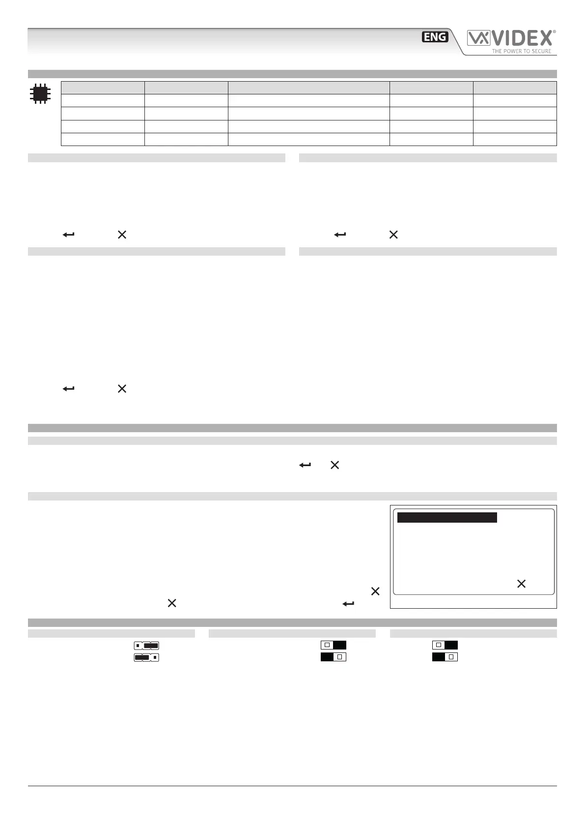
• press “5” and init the test. Now display will look like Fig. 10.
• the cental line describes the current test status; Flat, Ph. Id and Bl. Id specify which inter-
com is under test. Panel makes a call to every item stored in memory: if it receives the
acknoledge from intercom status will be OK and after 2 seconds skips to test the next
intercom. If no ack is received then status reports Fail: it is kept for 10 seconds. After that
time routine continues on testing next intercom. User can stop routine by pressing
:
test is paused. A further press of will end the routine. To resume test press .
JUMPERS, SWITCHES AND CONNECTION TERMINALS
JUMPERS
Dry contact output
Capacitor discharge
SWITCHES
Balanced V1, V2
Coax V2=V, V1 not used
RS485 BUS TERMINATION
Open
Close
stop
Testing...
Flat: 1
Ph. Id. 1
System-Test Connection
Fig. 10
Art.4212 Audio/video digital front panel Programming

 Loading...