66250203 - V4.4 - 15/05/22
- 16 -
4000 Series Vandal Resistant Range
Art.4212 - Installation instructions
Surface mounting door station installation
A
B
C
C
Fig. 1
B
Fig. 2
B
F
D
D
E
G
G
E
Fig. 3
Fig. 4
B
C
A
C
Fig. 5
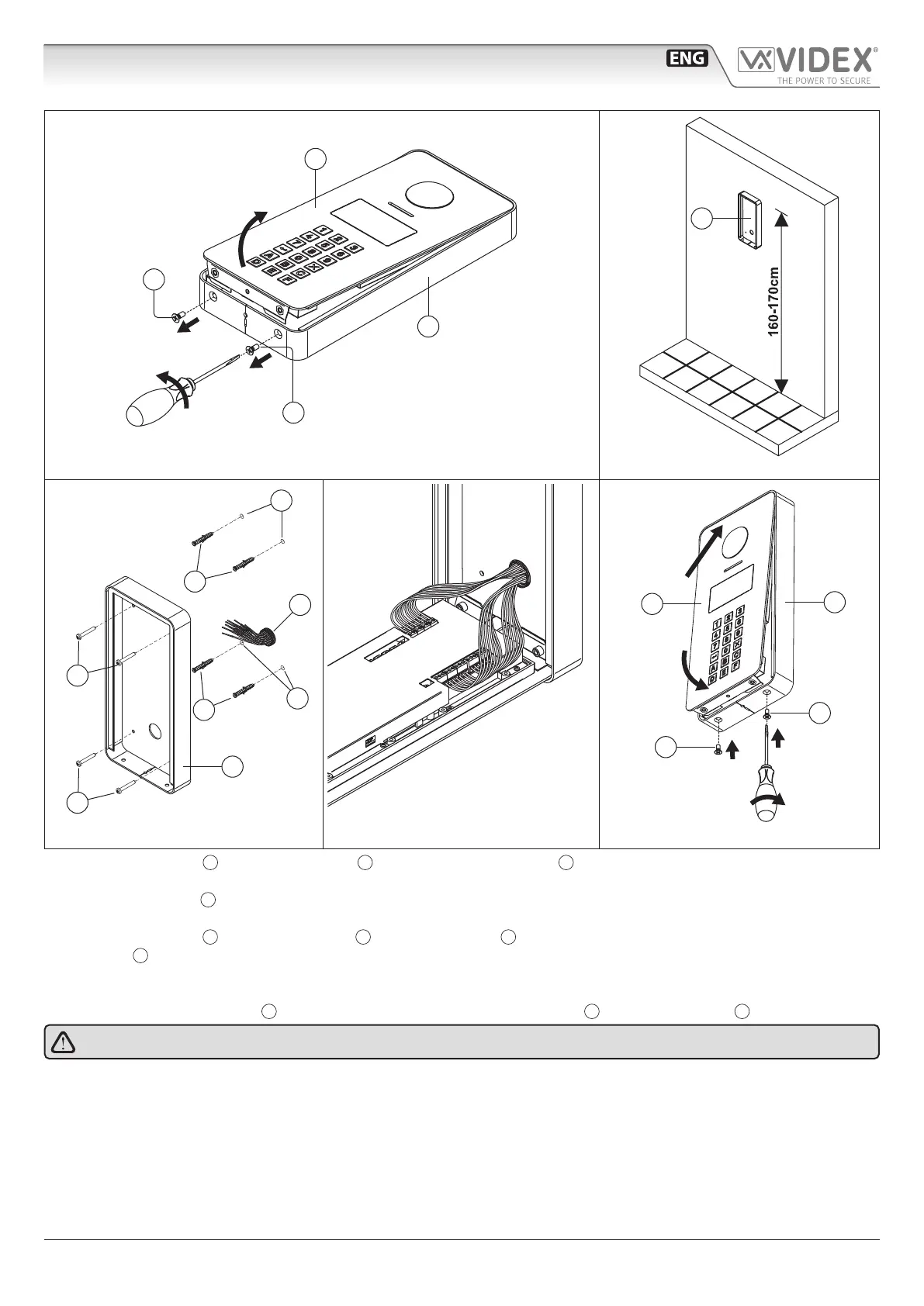
1. To separate the panel
A
from the surface box
B
, rst remove the two screws
C
located on the bottom of the surface box using
a screwdriver, then lever the panel from the bottom to extract it (Fig. 1);
2. Place the surface box
B
against the wall (165-170cm between the top of the box and the oor lever) and mark the 4 xing holes
for the wall plugs and the hole for the cables (Fig. 2);
3. Drill the 4 xing holes
D
, insert the wall plugs
E
and feed the cables
F
through the surface box, x surface box to the wall using
the screws
G
(Fig. 3);
4. Connect the wires using a terminal screw driver then setup the dip-switches as per provided connection diagram or instruction
sheet, then power up the system and check that it works correctly (Fig. 4);
5. Insert the top end of the panel
A
rst, then level down and x to the surface box
B
with the two screws
C
(Fig. 5).
Do not over tighten the screws more than necessary.

 Loading...