66251750-EN - V1.0 - 05/06/17
25
4000 Series Vandal Resistant Digital GSM - Technical Manual
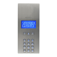
4000 Series Vandal Resistant Digital GSM Audio Intercom with Proximity
INSTALLING A FLUSH MOUNTING DOOR STATION
1. It is recommended that the ush box C is mounted into the wall approximately 165-170cm between the top of the box and the
oor level as shown in Fig.46.
2. Using the ush box C and the hole dimensions (w=120mm x h=263.2mm x d=46mm), as shown in Fig.47, use appropriate
tools to cut out the recommended hole size in the wall (where required it may be necessary to wear the appropriate clothing,
e.g. protective gloves and eye protection, when doing this). Remember to allow room for the connecting cables E (Fig.47);
Before tting the ush box C into the wall it is recommended that in order to prevent water ingress a silicon sealant is
used between the wall and the ush box C (Fig.48) and around the ush box openings D (Fig.48);
3. Set the ush box C into the hole in the wall feeding the connecting cables E through the appropriate ush box opening D, as
shown in Fig.49;
4. Follow steps 3 and 4, from ‘installing a surface mounting door station’ , to t the module into the module support frame H as
shown in Fig.37, Fig.38 and Fig.39 (on pages 22 and 23);
5. Next take connecting cables E and make the required terminal connections into the terminal block O using the screwdriver
provided P (using the at blade end), as shown in Fig.50;
6. Take the frame’s hinges L and hook the module support frame H to the ush box C, starting from the left following the guide arrows,
as shown in Fig.51. Ensure that the frame’s hinges L (Fig.51) t inside the relevant hinge mounts M inside the ush box C, as shown
in Fig.52;
7. Next close in the front support frame H and then pull it back from the ush box C while moving it slightly to the left, following
the guide arrows, as shown in Fig.53;
8. With the front support frame H opened out (to allow for easy access to the hinge mounts M) take the hinge locks N and clip them in
place locking into the hinge mounts M, following the guide arrows as shown in Fig.54;
9. Next open the module support frame H and clip the hinge locks N to the hinge mounts M, following the guide arrows, as shown
in Fig.54;
10. Plug the terminal block O (from step 5, Fig.50) into the module’s terminal block connector Q, as shown in Fig.55. Make any
other necessary panel adjustments required (connecting the antenna cable, tting the SIM card and setting the dip-switches
etc.);
11. After the system has been tested and is working correctly, move back the module support frame H carefully and then x it to the ush
box C using the screwdriver provided P (using the torx end) and the torx pin security screws provided R, as shown in Fig.56.
Note: do
not over tighten the screws more than is necessary.
NOTES
• The screwdriver’s blade has two sides, one at and one torx, to select one of them unplug the blade from the screwdriver body
and plug it into the required side.
4000 Series Back Box Installation