66251750-EN - V1.0 - 05/06/17
9
4000 Series Vandal Resistant Digital GSM - Technical Manual
4000 Series Vandal Resistant Digital GSM Audio Intercom with Proximity
Additional Components
Apart from the requirement of a SIM card additional parts will be required for the successful installation of the digital GSM. The
following components will also be required:
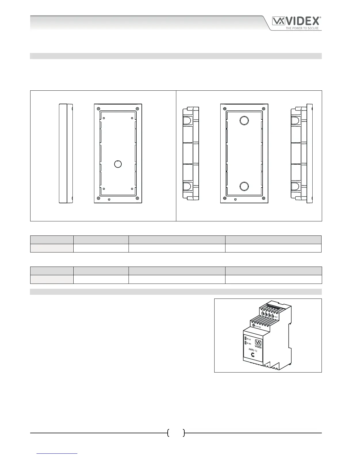
4000 SERIES BACK BOXES AND MOUNTING FRAMES
Both the Art.4812 and Art.4812R are designed to t the 4000 series range of back boxes and frames, both surface and ush back
boxes and mounting frames are available. The digital GSM requires a 2 module back box and frame. Front support frames are
available in a gun metal grey nish, chrome nish (sux \C to the frame code) or gold nish (sux \G to the frame code). The
following surface (see Fig.3) and ush (see Fig.4) options are available.
Fig. 3 Fig. 4
Surface Back Box Dimensions
Part No. Housed Modules No. of Columns Back Box (W x H x D) mm
Art.4882 2 1 135 x 280.2 x 43
Flush Back Box Dimensions
Part No. Housed Modules Front Frame (W x H x D) mm Back Box (W x H x D) mm
Art.4852 2 135 x 280.2 x 15.7 120 x 263.2 x 46
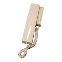
12VDC 2A POWER SUPPLY
The digital GSM intercom is designed to work with power supplies in the range
of 12Vdc to 14Vdc and should be capable of supplying a constant current of no
less than 2A. Typically the digital GSM can use a 12Vdc 2A power supply (refer
to Fig.5).
Fig. 5