30
ARTICLE
ARTICOLO
QTY
Q.TÁ
DESCRIPTION DESCRIZIONE NOTE NOTE
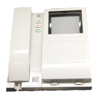
901/MV Videophone with memory board Videocitofono con memoria video
See at page 19 Vedere pag. 19
n..
521 Additional power supply Alimentatore supplementare
See at page 19 Vedere pag. 19
1
901 -M -F
901 Colour
Videophone Videocitofono n=user n=numero utentin..
890 Switchboard Centralino 1
850 Power transformer Trasformatore di alimentazione 1
852..-3.. Front support Sostegno portamoduli See type and qty at Pag. 11, 14
Per tipo e q.tà vedere a pag. 11, 14
2+n..
Camera module Modulo telecamera 2
837-0-1-2 Speaker unit module Modulo portiere elettrico 2
843.. -4.. -5..
Extension front panel module Modulo di chiamata See type and qty at page 10, 14
Per tipo e q.tà vedere a pag. 10, 14
n..
892 Switching device Scambiatore 2 posti esterni video 1
894 Video distribution box Distributore video di piano As may be required
Q.tà da stabilire in base alle esigenze
n..
CM10 Multicore cable-9+coax Cavo 9 fili + coax
Between control unit and videophone
Per colleg. centralino-videocit.mt
CM13 Multicore cable-12+coax Cavo 12 fili + coax
Between control unit and
outdoor
station
Per colleg. centralino-posto ester.mt
IIMMPPIIAANNTTOO
VVIIDDEEOOCCIITTOOFFOONNIICCOO
CCOONN
22
PPOOSSTTII
EESSTTEERRNNII
CCOOMMMMUUTTAABBIILLII
DDeessccrriizziioonnee
Questo impianto è impiegato negli edifici
che hanno 2 ingressi comuni a tutti gli
appartamenti. Si differenzia da quello a
n... utenti per l’impiego del dispositivo di
scambio Art. 892 che effettua la commu-
tazione di tutti i servizi sul posto esterno
in cui è stata effettuata l’ultima chiamata.
Se non c’è una conversazione in corso si
può effettuare l’autoaccensione pigiando
il pulsante (TV1), con l’inserimen-
to automatico del posto esterno da dove
è stata effettuata l’ultima chiamata. Se si
desidera autoaccendere un posto esterno
prioritario bisogna scollegare il filo TV1
dal centralino Art. 890 e collegarlo al mor-
setto “C” del posto esterno “A” o “B”; si
perde così il segreto di autoaccensione
ad impianto acceso.
RReeaalliizzzzaazziioonnee
iimmppiiaannttoo
a) Consultare la tabella a fondo pagina
per il materiale occorrente
b) Posare il cavo rispettando la sezione
dei dei fili (vedi pag. 18)
c) Collaudare impianto
(vedi a pag. 20)
SSeerrvviizzii
aauussiilliiaarrii
1) Suoneria supplementare (vedi pag. 22)
2) Con pulsante (TV2).
- accensione seconda telecamera (riferimento impianto pag. 37)
- accensione luci scale o altri servizi (vedere schemi applicativi pag. 22)
VVIIDDEEOOIINNTTEERRCCOOMM
SSYYSSTTEEMM
WWIITTHH
TTWWOO
AAUUTTOOMMAATTIICCAALLLLYY
SSWWIITTCCHHEEDD
OOUUTTDDOOOORR
SSTTAATTIIOONNSS
DDeessccrriippttiioonn
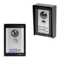
This type of installation is used in a buil-
ding with two entrances each with a push
button panel and one camera module.
The Art. 892 switching relay allows auto-
matic switching of video signal, speech
line and other services to the outdoor sta-
tion from where the call has been placed.
The recall button (TV1) can con-
nect videophone to the entrance from
where last call was placed.
The recall button (TV1) can be
connected in order to switch on one parti-
cular camera: on central unit Art. 890
disconnect wire TV1 and connect it to ter-
minal “C” of outdoor station “A” or “B” (by
doing this the “privacy” is lost).
IInnssttaalllliinngg
tthhee
ssyysstteemm
a) Consult the table below to obtain the
necessary items required.
b) Run the correct size cables (see page
18).
See block diagram for number of
cores.
c) Test installation (see page 20).
EExxttrraa
sseerrvviicceess
1) Additional speaker (see page 22).
2) Service button (TV2).
- Second TV camera (see page 37)
- Stairway light or other service (see page 22)
VM019280
830..
830 Colour