ENUK - V1.4 - 25/01/17
20
4000 Series GSM Audio Intercom - Technical Manual
4000 Series GSM Audio Intercom with Proximity
Wiring Diagrams
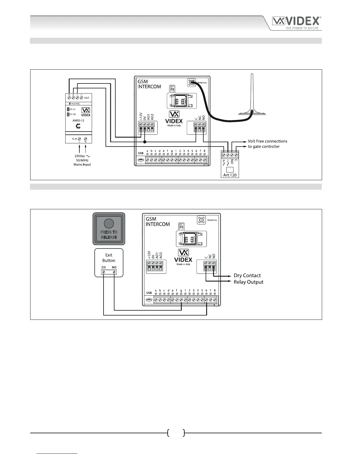
CONNECTING TO A GATE CONTROLLER USING THE ART.120 OPTOISOLATOR PCB
If the GSM intercom is going to be connected to a set of gate controls then it is recommended that the GSM relay is connected with
the Art.120 opto-isolator pcb provided with the GSM kit. The gate controls can then be connected into the C and NO terminals on
the Art.120 pcb. Follow the connections shown in Fig.17.
Fig. 17
CONNECTING A PUSH TO EXIT BUTTON
The push to exit button must be congured as a push-to-make switch and connected across terminals g & 6 on the Art.4810 GSM
module. When the exit button is pressed the GSM relay will trigger for the programmed time (see Fig.18).
Fig. 18