67009600-EN - Edition 2015 - Rev. 1.0
6
VX2300 Digital System - “2 Wire” Audio/Video Door Entry System
VX2300 Digital System - Installation handbook
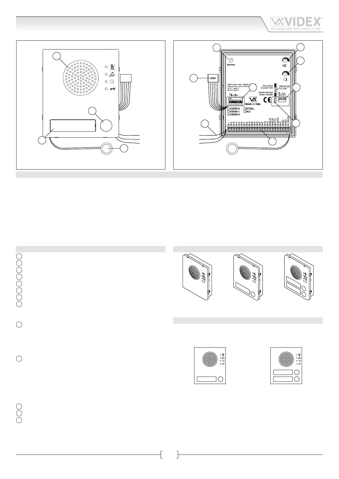
Art.4303N Speaker unit module with built-in functional to digital interface
White
Red
Blue
D
A
B
C
Fig. 1
White
Red
Blue
L
M
J I
K
G
H
F
E
Fig. 2
DESCRIPTION
Functional speaker module for up to 64 traditional call buttons. The unit circuitry incorporates :
• The transmitting amplier with condenser microphone and volume control;
• The receiving amplier with volume control;
• The audio balance circuit with the “BALANCE” control;
• The enslavement relay to enable the electric lock (3 contacts: common, normally open and normally closed). It can also operate
as capacitor discharge to power directly the electric lock;
• The call buttons from 0 to a maximum of 2 depending on the module version;
• The illumination LEDs for the card name holder.
The module is available in 3 versions according to the number of built-in push buttons.
MODULE DETALIS:
A
Loudspeaker;
B
Call push button (0 up to 2 according to the model);
C
Card name holder;
D
Microphone;
E
Balance control;
F
Loudspeaker volume Control;
G
Microphone volume control;
H
Door relay operating mode jumper:
• Lower position for capacitor discharge;
• Upper position for dry contacts;
I
Connector to supply button expansion modules:
• 3 modules can be connected between LD1 and GND;
• 3 modules can be connected between LD2 and GND;
• +V is 30V output with no current regulation to supply 3
button expansion modules connected in series;
J
Dip-switch to carry out the following programming:
• Door station ID (switches 1 to 3);
• Door opening time (switch 4);
• Conversation time (switch 5);
• Oset (switch 6);
• Camera selection order (switch 7);
• Art.2306 block mode (switch 8);
K
System connection terminals;
L
CNV connector to link to Art.4330N camera module;
M
Wires to congure built-in buttons:
• White = Common;
• Red = P1;
• Blue = P2
AVAILABLE MODULE VERSIONS
Art.4303N-0 Art.4303N-1 Art.4303N-2
BUTTONS LAYOUT
As factory preset, built-in buttons are congured to call address
1 or 1 & 2 but the setup may be changed by altering the position
of the 3 wires shown in Fig. 2 with reference “M”.
1
Art.4303N-1
1
2
Art.4303N-2
 Loading...


