The CAROUSEL MATE is a material handling and cutting machine designed to provide dependable service for maximizing efficiency in operations involving rolled goods, particularly carpet. It is built to meet or exceed current U.L. or C.S.A. standards.
Function Description:
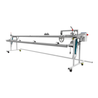
The CAROUSEL MATE is primarily used for accurately measuring and cutting rolled materials, such as carpet, from a carousel storage system. It features a counter display for precise length measurement, a cutting bar for making cuts, and a re-roller mechanism to re-roll the cut material. The machine is designed to be used in conjunction with a carousel that stores the rolled product.
Important Technical Specifications:
- Electrical Specifications: The machine is factory-equipped for use on a circuit with a nominal rating of more than 120 volts. Older Durant counters used on the Carousel Mate were 220 volts, while those used on Archer cutting machines were 110 volts. The current interface and PLC are designed for 120 volts (as of April 17, 2009). A dedicated power line and circuit breaker with suitable conductor wire connections and ampere rating are recommended. The PLC (Part # 409-0055) operates on 100 to 240 volts.
- Counter Display: Modern units (since November 2009) use a 4-arrow key display. Older units (before November 2004) used a 5-arrow key display, which requires a PLC upgrade to be compatible with the current 4-arrow display. The counter display should be accurate to within ½ inch of 10 feet for calibration.
- Calibration Factors: The machine has factory pre-set calibration factors for accurately measuring carpet. There are screens for "Carpet1," "Carpet2," and "Vinyl," but only "Carpet1" is used for the Carousel Mate. The factory default setting is designed for standard carpet.
- Unit of Measure: Users can select between Imperial (feet and inches, default) and Metric units.
- Cutter Blades: The machine uses cutting blades (Part # 103-0012). A box of 100 blades is available (Part # 103-0033).
- Encoder: The encoder (Part # 402-0042) works with the PLC. When functioning correctly, PLC Input Lights 0 and 1 will flash alternately. The encoder output should provide 0 to 9 volts when slowly spinning the shaft, with an input of 12-28 volts DC.
- Retractable Cord Reel: (Part # 406-0013)
- Interface: (Part # 409-0057)
- Cables: PLC to Display cable (part # 406-0087 - crossover cable, may or may not be needed), PLC to Interface cable (Part # 409-0080).
Usage Features:
- Operation:
- Position the Carousel Mate in front of the desired product roll.
- Ensure the top of the material roll is 1" below the top of the table to prevent inaccurate counts.
- Remove Velcro straps from the roll.
- Raise the counter hold-down weight.
- Flip/pull the material onto the table, ensuring the backing side is down to contact the knurled counting wheel for accurate readings.
- Pull the material edge to the cutting bar groove.
- Lower the counter hold-down weight.
- Reset the counter to zero.
- Ensure the re-roller is in place and its levers/latches are locked.
- Grasp the material and pull it to the center of the re-roller tube.
- Clamp the material to the re-roller tube.
- Use the crank to roll the desired length onto the re-roller.
- Lock the material to the table with clamps.
- Recheck the counter for correct length.
- Use the cutting bar handle crank to make the cut.
- Wrap the cut product.
- Place a cart under the cut product.
- Lower the product onto the cart by pulling the release pin up and gently pulling the lever forward to lower the roll.
- Release re-roller latches by turning the nut counter-clockwise.
- Remove the re-roller from the cut product and place it back on the Carousel Mate.
- Re-roll the product back onto the main roll and secure with Velcro straps (minimum 3 per roll).
- Counter Functions:
- Black Keys (Data Entry): Used for numeric data entry, especially for password and setup.
- White Arrows: Used to navigate machine setup screens.
- DELETE button: Clears the counter value to zero.
- MOD button: Used to select the Master Password entry screen during setup.
- ENTER button: Used to confirm entries.
- Password Protection: The machine has an optional password protection feature. When enabled, a password must be entered upon startup. The factory preset disables this feature. There is a User Password (changeable) and a Master Password (factory set, contact Vidir Support if unknown). A Password Timer can be set to require re-entry after a period of inactivity.
- Setup Mode: Accessed by pressing and holding the left arrow, then pressing and releasing the down arrow, then releasing the left arrow. The MOD button is used to select the Master Password entry screen. The only way to exit the Master Menu is to turn off the power.
Maintenance Features:
- Blade Change:
- Move the cutter to a suitable working location.
- Press the blade lock latch release lever (A).
- Lift the blade lock latch (B) to release the blades.
- Slide the blade up and out, flip, and insert again (C). Caution: Cutting blades are sharp.
- Counter Calibration Check:
- Place a tape measure under the counter hold-down weight.
- Lower the hold-down weight.
- Pull the tape measure until the hook is at the cutting bar edge.
- Reset the counter to zero.
- Pull the tape measure until the 10-foot mark is at the cutting bar edge.
- Read the counter display. It should be within ½ inch of 10 feet.
- Repeat the test if the reading is inaccurate. If consistently off, recalibration is needed (contact Vidir Service).
- Preventative Maintenance Checklist (Recommended Every 100 Hours or 12 Months):
- Inspect guide rail for damage.
- Check retractable cord reel for proper function.
- Inspect cord end for damage.
- Check counter calibration with a tape measure.
- Ensure counter wheel spins freely.
- Clean and lubricate caster wheels.
- Check rear plastic track wheels.
- Check cutter chain tension.
- Ensure re-roller latches are in good condition and working properly.
- Inspect and change cutter blades as needed (clean debris from blade slots).
- Inspect and lube re-roller drop-down pivot points.
- Inspect re-roller drop-down latch mechanism for proper operation.
- Troubleshooting:
- Poor cutting quality: Dull blades, operator cutting too fast, drive roller wheels not lowered, material buildup on blades (spray with silicone).
- Uneven cuts: Incorrectly installed spacer collars, loose set screws, material not kept against the edge guide.
- Display screen shows wrong information: Reprogram the display (contact Vidir Service).
- Cutter Cover Retrofit: Instructions are provided for installing a cutter cover, including hold-down arm spacer installation. If the cover does not fit, contact Vidir for a cover for the slim-style cutter.
- Double Blade Holder Removal Procedure: Detailed steps are provided for removing the cutter assembly, including loosening chain tension, removing the chain cover, pulling the chain off the sprocket, and detaching master links. Reinstallation is the reverse procedure.