Data sheet
Burner System Loader System
PYROMAT-DYN
1
Köb Holzheizsysteme GmbH, Flotzbachstr. 33, A-6922 Wolfurt, Tel. +43/5574/6770-0, Fax 65707, E-Mail: office@kob.cc
Subject to technical changes
3010-2
2009-03-01_GB
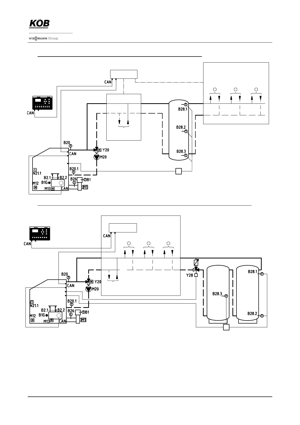
Schematic diagram with ECOTRONIC
a) DYN with reduced log operation (standard with accumulator as hydraulic switcher)
b) DYN with full ECO-function in log operation (accumulator volume as per EN 303-5 – see Spec Sheet 3950)
With this variation, the
heat accumulator is incorporated by a storage control valve [Art. No. LSR-DYN-]
ECOTRONIC with heating control unit
The ECOTRONIC can be expanded by a great number of heating control units (heat consumers, additional heat
generators) (refer to spec sheets, Category 4). The operation of the heating control units is all carried out in the control
module for the burner system. Each controller is operated by a separate pushbutton.
For ECOTRONIC expansion possibilities, refer to spec sheets, Category 4
PYROMAT-DYN with integrated manifold
One manifold with two or three consumer groups can be integrated with the PYROMAT-DYN burner. In this design with
the manifold attached, the burner forms a compact overall system (refer to Spec Sheets 4600).
+
F8
OK
-
F7
>
KÖB
F6F5
>
<
F3 F4F1 F2
>
accumulator as
hydraulic switcher
accumulator
additional
heat generator
3
21
heat consumer
control
module
control system module
ECO-RM-00
Pyromat-DYN
control
module
heat consumer
additional
heat generator
1 2 3
control system module
ECO-RM-00
accumulator
2
accumulator
1
Pyromat-DYN
+
F8
OK
-
F7
>
KÖB
F6F5
>
<
F3
F4F1 F2
>