131
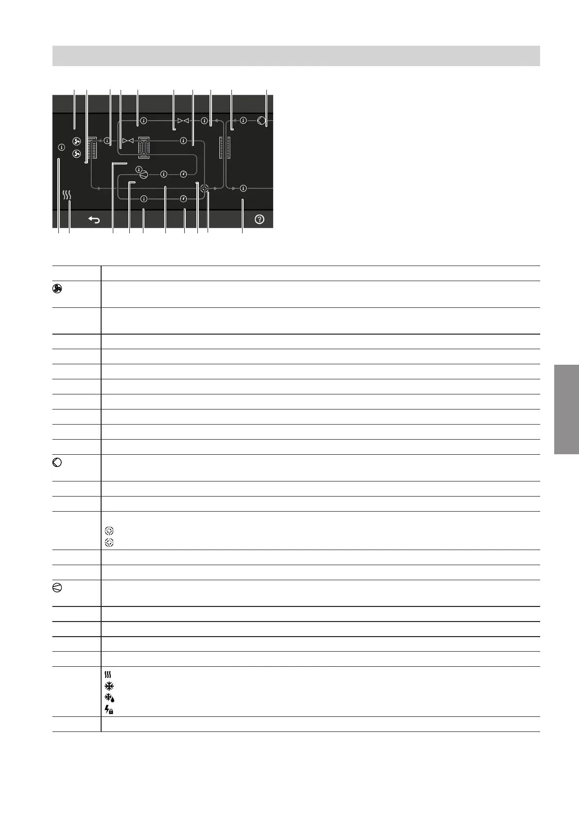
Refrigerant circuit overview
46 %
41 %
16 °C 43 %
28.7 °C 68 %
14.8 °C
46.2 °C 44.7 °C
59 %
46.7 °C
6.3 bar
26.6 °C
40 %
16.4 bar54.2 °C
48.9 °C
AB CD E F G K L
VW S P N MRTU
H
O
22.6 °C
Fig. 87
Pos. Meaning
Fan
Animated symbol: Fan is running.
A
Only outdoor units with 2 fans:
Speed of fan 2 in %
B
Speed of fan 1 in %
C
Liquid gas temperature – cooling, in °C
D
Aperture width of electronic expansion valve 2 in %
E
Liquid gas temperature – heating, in °C
F
Aperture width of electronic expansion valve 1 in %
G
Suction gas temperature – evaporator, in °C
H
Liquid gas temperature – condenser, in °C
K
Secondary circuit return temperature in °C
Secondary pump
Animated symbol: Pump is running.
L
Secondary pump speed in %
M
Secondary circuit flow temperature in °C
N
4-way valve, refrigerant circuit
Heating mode
Cooling mode
O
Suction gas pressure – compressor, in bar
P
Condensing pressure – compressor, in bar
Compressor
Animated symbol: Compressor is running.
R
Suction gas temperature – compressor, in °C
S
Hot gas temperature in °C
T
Position of compressor in %
U
Compressor temperature in °C
V
Heating mode
Cooling mode
Defrost
Power-OFF
W
Evaporator air intake temperature in °C
System configuration and diagnostics
Diagnostics (cont.)
6222080
Diagnosis