78
To check this, the resistance at one of the CAN bus
connections between CAN L and CAN H can be meas-
ured after all CAN bus connections have been comple-
ted: Target value 60
Ω
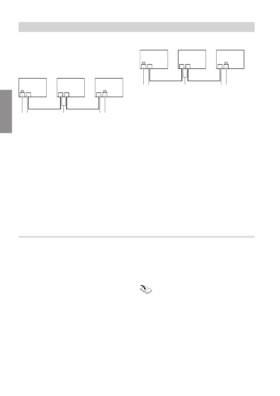
The heat pump is the first or last subscriber
Fig. 58
A Heat pump connected as first or last CAN bus sub-
scriber
In this case, 1 connection is required on the heat
pump:
■
1 connection in the extra low voltage (ELV) ter-
minal area < 42 V on the upper luster terminal,
terminals 6 and 8
Connection 91
Do not connect CAN Ground (GND)!
■
Do not remove the factory-fitted plug 91 in the
HPMU electronics module.
This plug contains the terminator.
B CAN bus cable
C Other CAN bus subscribers
D
Connection of external CAN bus without terminator
E
Connection of external CAN bus with terminator
The heat pump is the central subscriber
Fig. 59
A Heat pump as central CAN bus subscriber
In this case, 2 connections are required on the
heat pump:
■
1 connection in the extra low voltage (ELV) ter-
minal area < 42 V on the upper luster terminal,
terminals 6 and 8
Connection 91
Do not connect CAN Ground (GND)!
■
1 connection in the HPMU electronics module:
Remove the factory-fitted plug 91. Insert the
BUS cable (accessories) into the same slot.
Or for wiring on site:
1 connection at plug 91 inserted on site on
HPMU electronics module: Remove terminator
from this plug 91.
Do not connect CAN Ground (GND)!
B CAN bus cable
C Other CAN bus subscribers
D
Connection of external CAN bus without terminator
E
Connection of external CAN bus with terminator
Connecting the energy meter
The energy meter is installed on the main distribution
board. It is connected to the building's power supply
and to the external CAN bus system according to the
connection diagrams in the system schemes.
Recommended cable type: See chapter "Connecting
with other Viessmann appliances via the CAN bus".
!
Please note
Incorrect core assignment can result in appli-
ance faults.
Never interchange wires.
CAN BUS ID
The node ID "ID 97" is preset.
If 2 energy meters are used within a CAN bus system,
the node ID must be changed to "ID 98" for one of
them.
Installation and service instructions for the
"Energy meter"
Electrical connections
Electrical connection of the indoor unit (cont.)
6222080
Installation