77
Some accessories with direct power supply
74
74
40A
40
74
74
40A
40
B C
74
40
156
A
74
74
40A
40
D
E
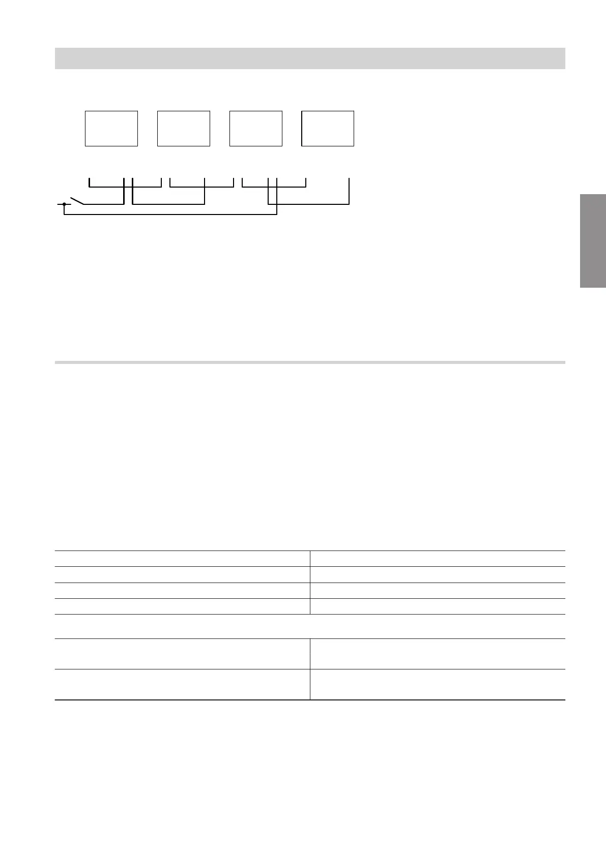
Fig. 57
A
Indoor unit terminal areas
40 Control unit/PCB power supply in the 230 V~
terminal area
74 Connecting PlusBus to the upper luster termi-
nal in the low voltage (ELV) < 42 V terminal
area
156 Power supply for PlusBus subscribers in the
HPMU electronics module
B
Mixer extension kit
C
Mixer extension kit
D
Mixer extension kit
E
ON/OFF switch
Connecting with other Viessmann appliances via the CAN bus
The heat pump can form a system network with other
compatible appliances via the external CAN bus. Com-
bining Viessmann appliances with One Base brings
benefits such as shared use of a connectivity module
or even joint commissioning and operation via an app.
■
The Viessmann CAN bus is designed for "line" bus
topology with a terminator at both ends: See Fig. 58.
■
With CAN bus, the transmission quality and the
cable lengths depend on the electrical properties of
the cable.
■
Only use one cable type within a CAN bus.
Note
Commissioning of all CAN bus subscribers: See chap-
ter "Commissioning the system".
Recommended cable
■
Recommended cable:
Bus cable (accessories), length: 5, 15 or 30 m
■
For wiring on site:
Only use cable types listed in the following tables.
Recommended cable type (on site):
CAN bus cable In line with ISO 11898-2, twisted pair cable, shielded
■
Cable cross-section
0.34 to 0.6 mm
2
■
Characteristic impedance 95 to 140 Ω
■
Max. length (entire CAN bus system) 200 m
Alternative cable types (on site):
CAN bus cable 2-core, CAT7, shielded
■
Max. length (entire CAN bus system) 200 m
CAN bus cable 2-core, CAT5, shielded
■
Max. length (entire CAN bus system) 200 m
Terminator for external CAN bus system
When integrating into an external CAN bus system, a
distinction is made as to whether a CAN bus sub-
scriber is the first, last or central subscriber.
In order to avoid communication interferences, only
1 terminator with 120 Ω may be present at the first and
last subscriber for the termination of the external CAN
bus system.
If the heat pump is connected as the central sub-
scriber, the factory-connected terminator must be
removed: See the following chapters.
Electrical connections
Electrical connection of the indoor unit (cont.)
6222080
Installation