15
Indoor unit with 2 integral heating/cooling circuits
1 or 2 heating/cooling circuits without mixer can be
connected to the heat pump.
■
Heating/cooling circuit 1:
The flow temperature is controlled by modulating the
heat pump.
■
Heating/cooling circuit 2:
The flow temperature is controlled by the mixing
function of the 4/3-way valve and the speed of the
built in heating circuit pump dependent upon the flow
temperature in heating/cooling circuit 1.
Therefore, in room heating mode, the maximum flow
temperature of heating/cooling circuit 2 cannot be
higher than the current flow temperature of heating/
cooling circuit 1.
In room cooling mode, the flow temperature in heat-
ing/cooling circuit 2 cannot lie below that of heating/
cooling circuit 1.
Note
Only connect heating/cooling circuit 2 if heating/cool-
ing circuit 1 is also connected.
System with external buffer cylinder
Indoor unit with 1 integral heating/cooling circuit
■
Up to 4 heating/cooling circuits can be connected to
the heat pump:
1 heating/cooling circuit without mixer and up to
3 heating/cooling circuits with mixer
■
An external cooling water buffer cylinder or external
heating/cooling water buffer cylinder is required to
use the cooling function.
Indoor unit with 2 integral heating/cooling circuits
An external buffer cylinder cannot be connected.
External heat generator (on site)
An external buffer cylinder is always required for sys-
tems with an external heat generator. Therefore for
heat pumps with 2 integral heating/cooling circuits
(types ... 2C), an external heat generator cannot be
integrated into the system.
The external heat generator is hydraulically integrated
into the system downstream of the external buffer cyl-
inder. The EM-HB1 extension (accessories) is required
for control via the heat pump.
The external heat generator supports the heat pump
with room heating if the heating output of the heat
pump is insufficient under certain conditions. In power-
OFF mode or if the heat pump develops a fault, the
external heat generator can also be switched on as the
sole heat source, e.g. for frost protection of the sys-
tem, including the outdoor unit.
Note
DHW is always heated by the heat pump or the instan-
taneous heating water heater installed in the indoor
unit.
Heat pump control unit
The heat pump control unit built into the indoor unit
monitors and regulates the entire heating system.
The indoor and outdoor units communicate via CAN
bus.
The following operating elements can be used to make
settings and perform checks on the system:
■
ViGuide, ViCare app
■
HMI programming unit of the heat pump control unit:
Operating instructions for the heat pump
■
Wireless remote control, if installed:
Operating instructions, installation and service
instructions for the remote control
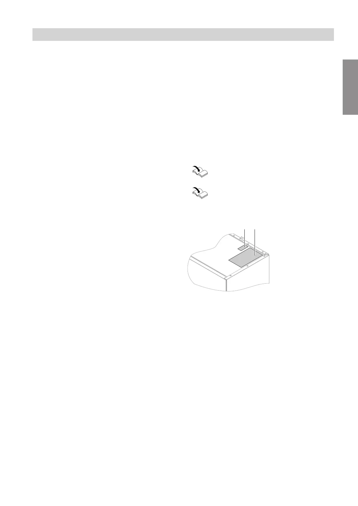
Type plate
Fig. 1
A
Type plate
B
QR code for appliance registration
Alternatively, the QR code is located on the type
plate.
The QR code with designation "i" contains the
access data for the registration and product informa-
tion portal.
Using this QR code, the 16-digit serial number,
for example, can be read out.
Information
Product information (cont.)
6222080
Information