172
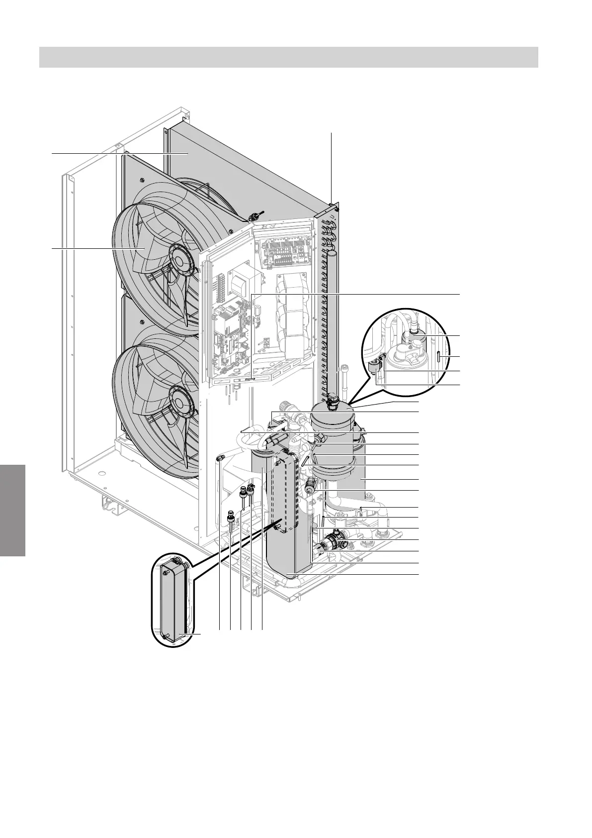
Outdoor unit with 2 fans, types ...A10 to A13
wE
wW
wQ
qO
qI
qU
qZ
qT
qR
qE
qW
qP
9
8
7
6
5
4
3
1
2
wP
qQ
wI wRwTwZwUwO
Fig. 116
1
Fan
2
Evaporator
3
Air intake temperature sensor
4
Interior temperature sensor
5
Accumulator (refrigerant receiver) compressor
6
Liquid gas temperature sensor, cooling
7
Schrader valve, low pressure side
8
Electronic expansion valve 2
9
Float air vent valve with quick-action air vent valve
qP
4-way diverter valve
qQ
Suction gas temperature sensor, evaporator
qW
Secondary circuit flow temperature sensor
qE
Liquid gas temperature sensor, condenser
qR
Hot gas temperature sensor
qT
Compressor
qZ
Electronic expansion valve 1
qU
Oil sump temperature sensor
qI
Compressor temperature sensor, compressor
qO
Schrader valve, high pressure side 1
wP
Ball valve with filter
Outdoor unit maintenance
Overview of internal components (cont.)
6222080
Maintenance