174
qE
Suction gas temperature sensor, evaporator
qR
High limit safety cut-out
qT
Float air vent valve with quick-action air vent valve
qZ
Schrader valve, evaporator
qU
Compressor including oil sump heater
qI
Oil sump temperature sensor
qO
Compressor temperature sensor, compressor
wP
Ball valve with filter
wQ
Non-return valve
wW
Condenser
wE
Schrader valve, low pressure side
wR
Internal heat exchanger
wT
High pressure sensor
wZ
Low pressure sensor
wU
High pressure switch PSH
wI
Accumulator (refrigerant receiver)
wO
Liquid gas temperature sensor, condenser
eP
Interior temperature sensor
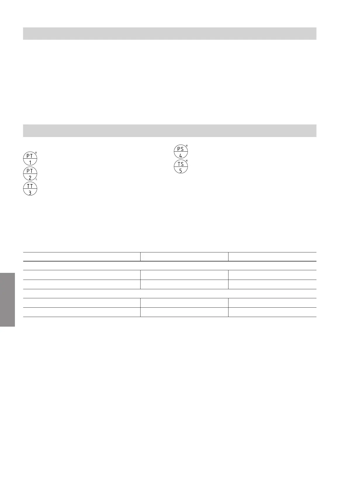
Refrigerant circuit flow diagrams
Labelling of the sensors in acc. with EN 1861:
High pressure sensor
Low pressure sensor
Temperature sensor
High pressure switch PSH
High limit safety cut-out
Note
The following two flowcharts for heating operation and
cooling operation apply to outdoor units with 1 and
2 fans. The outdoor unit with 2 fans is shown as an
example.
Flow rates
Outdoor unit for heat pump types ...A04 to A13 ...A16 to A19
Secondary-side flow rates (heating water)
■
Minimum flow rate
0.350 m
3
/h (350 l/h) 0.350 m
3
/h (350 l/h)
■
Max. flow rate
2.050 m
3
/h (2050 l/h) 2.070 m
3
/h (2070 l/h)
Primary side flow rates (air)
■
Minimum flow rate
2900 m
3
/h 3432 m
3
/h
■
Max. flow rate
5300 m
3
/h 5400 m
3
/h
Outdoor unit maintenance
Overview of internal components (cont.)
6222080
Maintenance