35
H
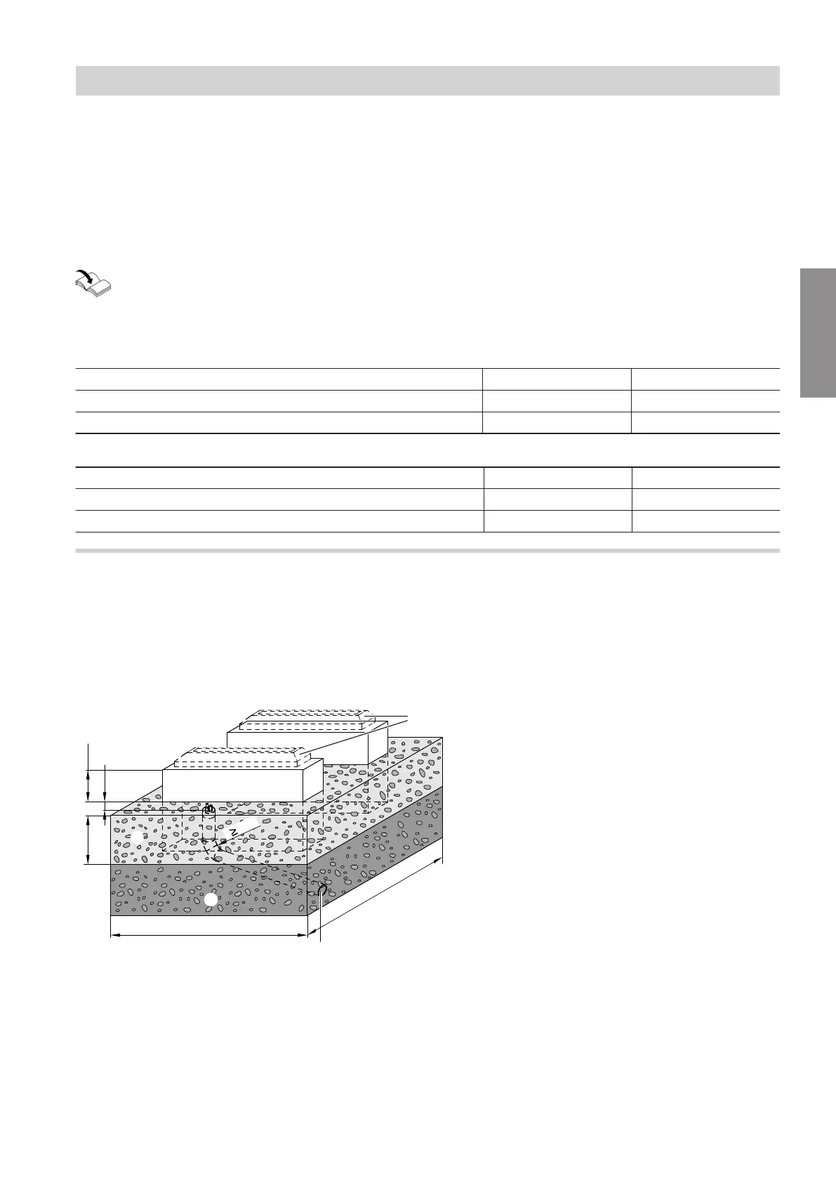
Wall
K
Flexible separating layer between the foundations
and the wall, in accordance with local require-
ments and the standard rules of building engi-
neering
a, b For line entries below ground level only: See the
following tables.
r Bending radius
Installation with support for floorstanding installa-
tion (accessories)
Installation instructions for "support set for floor-
standing installation"
Use M10 x 80 ground anchors with a tensile
force of at least 2.5 kN to secure the support.
When laying the Quattro connection line in a straight trench
Vitocal a b
Types ...A04 to ...A13 ≥ 940 mm 175 mm
Types ...A16 to ...A19 ≥ 980 mm 215 mm
When laying the Quattro connection line in a trench with a bend
Vitocal a b
Types ...A04 to ...A13 ≥ 250 mm 175 mm
Types ...A16 to ...A19 ≥ 290 mm 215 mm
Foundation for installation with anti-vibration base (accessories)
Provide 2 horizontal foundation strips.
■
Max. tilt tolerance: ±10 mm for every 1 m of length
Recommendation: Construct concrete foundations in
accordance with the following diagram. The stated
thickness of the layers represents an average value.
These values should be adjusted to suit the local con-
ditions. Observe the standard rules of building engi-
neering.
850
F
1550
A
400
C
r 600
E
150
B
B
10
Fig. 19
Siting the outdoor unit
Floorstanding installation (cont.)
6222080
Installation