71
Terminal area 230 V~/400 V~
40
P2P1171143
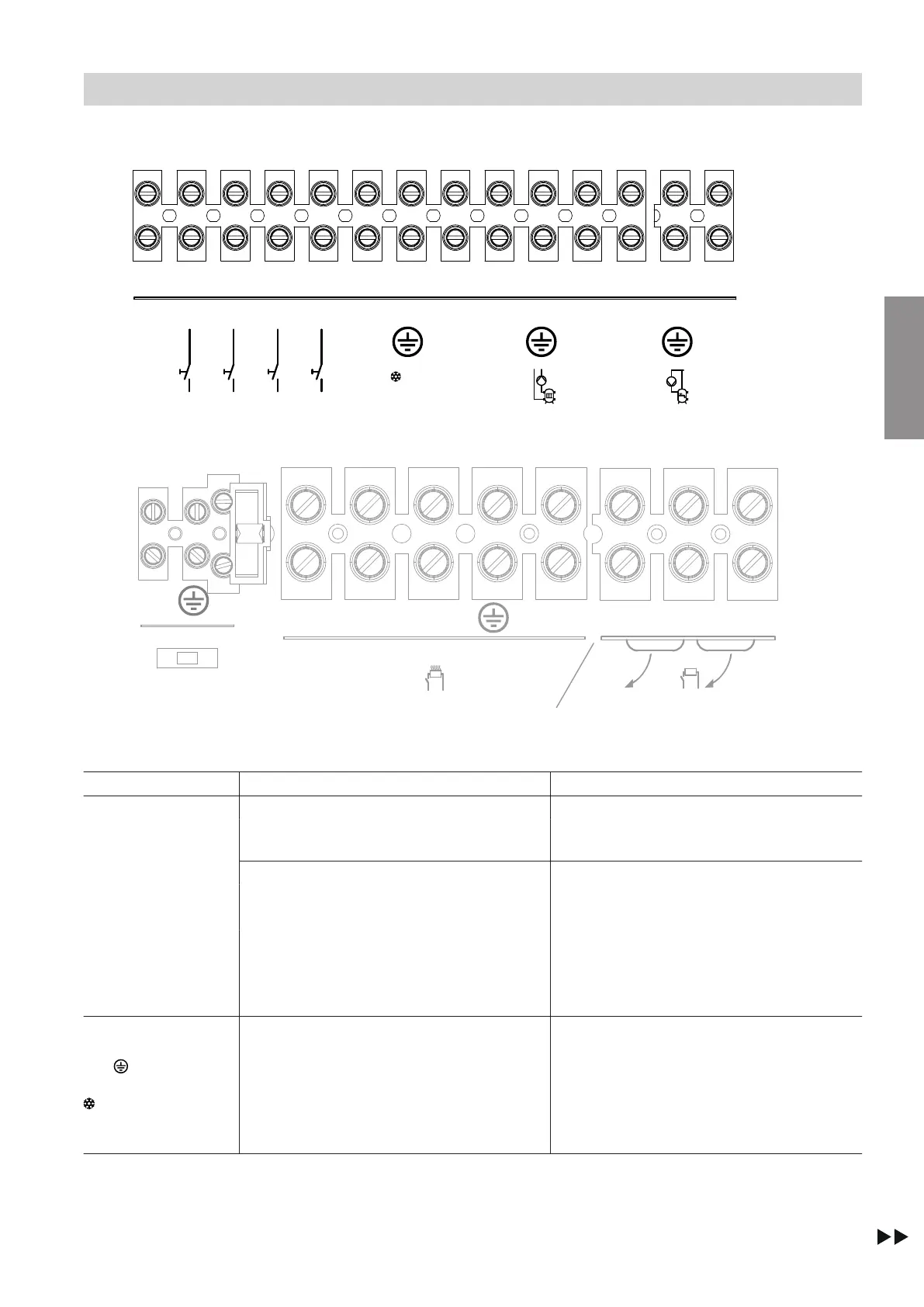
1 2 3 4 5 6 7 8 9 10 11 12 13 14
N L N L N L
N
L
NL1 L2 L3 N1 N2 N3
136
136
1
1/N/PE
230 V/50 Hz
3/N/PE
400 V/50 Hz
1/N/PE
230 V/50 Hz
230 V~
3x
AC
r
r
C
F2
Fig. 54
Upper luster terminal
C
: 230 V~ components and digital inputs
Terminals Component/function Explanation
1 to 5
143.1 Power supply for configurable digital in-
puts 143.2 to 143.5
Voltage: 230 V~
143.2
Configurable digital inputs 143.2 to 143.5
Possible functions: See chapter "Digital in-
put functions"
Set the required parameters during commis-
sioning: See chapter "Commissioning assis-
tant"
Breaking capacity: 230 V~, 0.15 A
Recommended connecting cable:
■
2 x 0.75 mm
2
■
Max. cable length: 50 m
143.3
143.4
143.5
6 to 8
171.N
171.
171.L
AC
Control of cooling
"Active cooling" function
■
Output: 230 W
■
Voltage: 230 V~
■
Max. switching current: 1 A
Recommended connecting cable:
■
3 x 1.5 mm
2
■
Max. cable length: 50 m
Electrical connections
Electrical connection of the indoor unit (cont.)
6222080
Installation