52
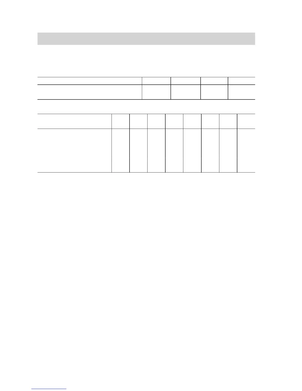
Maximum flue length
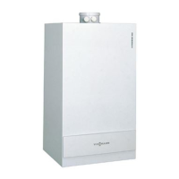
Vitodens 100-W
Rated heating output kW 19.0 26.0 30.0 35.0
System size 60/100 m 20 20 15 15
System size 80/125 m 25 25 20 20
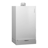
Vitodens 200-W, 222-F and 242-F
Rated heating
output
kW 13 19 26 35 45 60 80 100
System size
60/100
m 20 20 20 15 — — — —
System size
80/125
m 25 25 25 20 12 12 — —
System size
100/150
m — — — — 17 17 20 20
Note
For alternative system sizes, a bal-
anced flue adaptor is required.
The following components are taken
into consideration for the maximum flue
lengths:
■ 2 balanced flue bends 87°
Subtract other bends, tees and straight
lengths from the maximum length using
the following values:
■ Balanced flue bend 45°: 0.5 m
■ Balanced flue bend 87°: 1 m
■ Balanced flue inspection tee: 0.5 m
Installation
1. Create an opening in the wall (min.
diameter):
■ 105 mm (system size 60)
■ 130 mm (system size 80)
■ 160 mm (system size 100).
2.
Push external wall bend 8 with
wall bezel
5
into the wall opening
from the outside.
3.
Fit air inlet section 9 as near as
possible to external wall bend
8
.
4.
Secure interior wall bezel 5.
5. Connect the balanced flue connec-
tion pipe from the inside and route
with a fall of min. 3° (approx.
50 mm/m) towards the boiler.
6.
Use external wall clamps 6 to fit
the flue components to the external
wall at a consistent distance.
Position external wall clamps
6
in
intervals of max. 2 m.
Routing over an external wall
(cont.)
5780 223 GB
 Loading...