Installation Guide MX1 Fire Alarm System (NZ)
LT0360 ISSUE 2.43 29 NOVEMBER 2017 PAGE 10
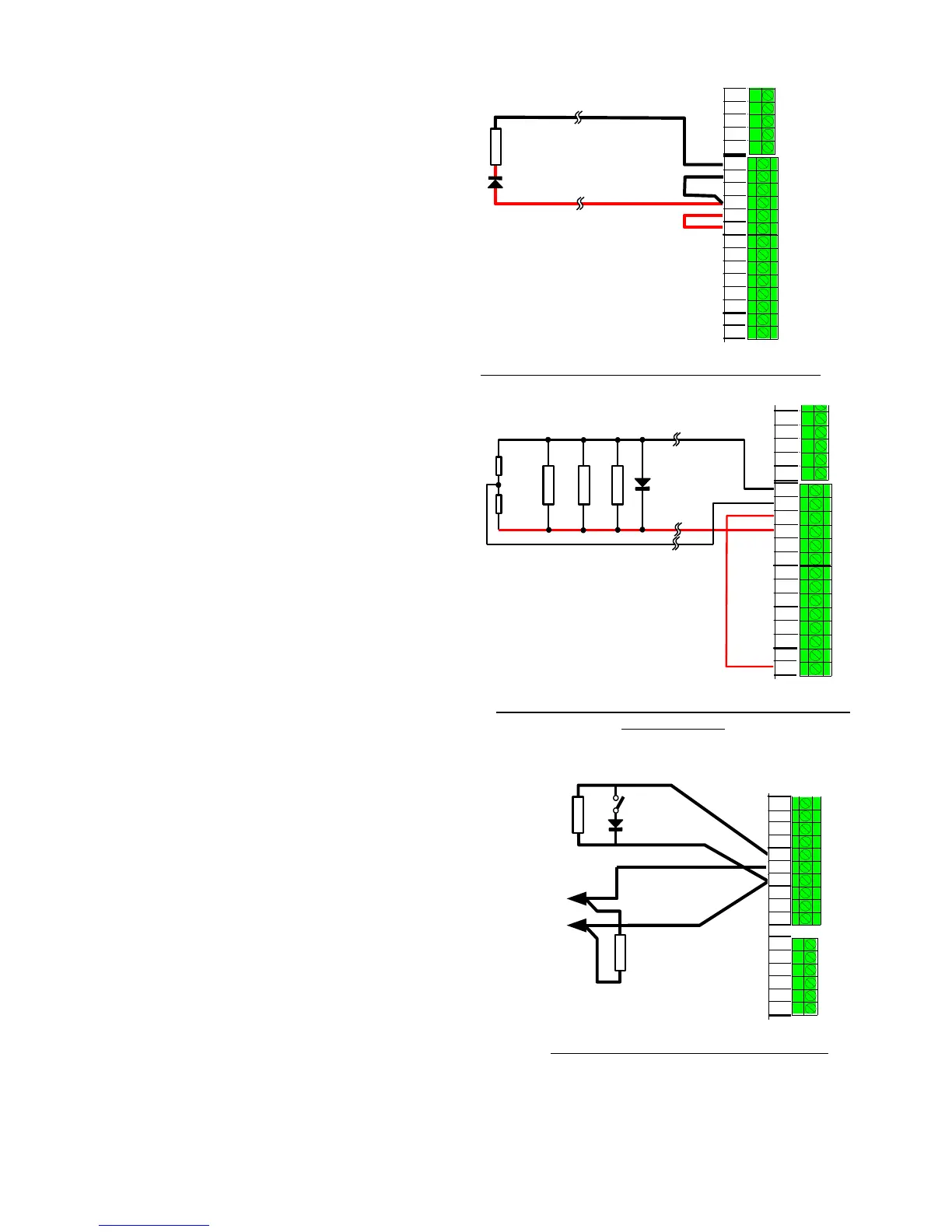
Ancillary Relay Load Supervision
Ancillary relays ANC1 and ANC2 can be used
to supervise load wiring for short and open
circuit faults, using the wiring shown in
Figure 11.
Full supervision is only possible for a single
load, or multiple loads wired in series. Multiple
parallel loads cannot be reliably supervised.
The load can be wired directly if its resistance
is 400 to 18k. Loads of less than 400
require a series diode for correct supervision.
A suitable diode is 1N5404. The minimum
rated load is 25.
The MX1 must be configured to have the
supervision input operate in “load” mode.
Load
Series diode
is required if
load is less
than 400
ohms
MX1 CONTROLLER
ANC RELAY 1
ANC RELAY 2
ANC RELAY 3
0V
SUP
NC
C
VBF+
NO
Figure 11 – Wiring for switched load with supervision
Figure 12 shows wiring for a method of connecting
normally-energised loads such as door holders to the
ancillary relays, powered from the non-battery-backed
supply VNBF, and with wiring supervision.
This method supervises both supply leads, and can
be used with either ANC1 or ANC2 relays. The two
EOLRs must have the same value, but this can be
anything between 2.7k and 27k. Either of the
18k or 27k EOLRs provided with the MX1 are
suitable.
Inductive loads such as door holders must have a
suppression diode connected as shown. A suitable
diode is 1N5404.
Note that ANC1 and ANC2 contacts are only rated at
1A inductive at 30V.
The MX1 must be configured to have the supervision
input operate in “door holder” mode.
Normally
energised loads
EOLR
EOLR
EOLR values can
be from 2k7-27k,
but must be the
same value
MX1 CONTROLLER
ANC RELAY 1
ANC RELAY 2
ANC RELAY 3
0V
SUP
NC
C
VNBF+
NO
VBF+
Suppression
diode
Figure 12 – Wiring to Normally-Energised VNBF Loads
with supervision
General Purpose Inputs (IN1, IN2)
MX1 has two identical protected inputs which can be used
for supervised connection to clean contacts or open
collector style outputs of other equipment, e.g., sprinkler
FBA/DBA.
Figure 12 shows examples of connection to a normally-
open contact and to an open collector output, both with
defect supervision. The EOLRs can be any value between
1.5k and 3.3k; 2.7k EOLRs are provided with the
MX1. The diode can be any general purpose silicon diode
such as 1N4004.
If supervision is not required, the EOLR can be omitted. If
short circuit defect supervision is not required, the diode
can be omitted, i.e., wired through. Note that short circuit
supervision is not possible for a connection to an open
collector output.
The MX1 must be configured with user logic or a zone
mapping for these inputs to produce any effect. There is
no default action.
MX1 CONTROLLER
EOLR
EOLR
ANC RELAY 1
VBF+
OUT 1
OUT 2
IN 1
IN 2
0V
Figure 13 – Wiring General Purpose Inputs