EasyManua.ls Logo

Vigilant MX1-Au - User Manual

Default Icon
182 pages
Print Icon
To Next Page IconTo Next Page
Loading...
Vigilant MX1-Au
Fire Alarm System
Operator
Manual
LT0439
Issue
1.73
Vigilant MX1
Sample MX1 Fire Alarm System
MX1 V1.70 AS 7240.2 15:04:07
Normal 30/11/17

Table of Contents

Other manuals for Vigilant MX1-Au

Questions and Answers

  • R
    Ricky BairdSep 10, 2025
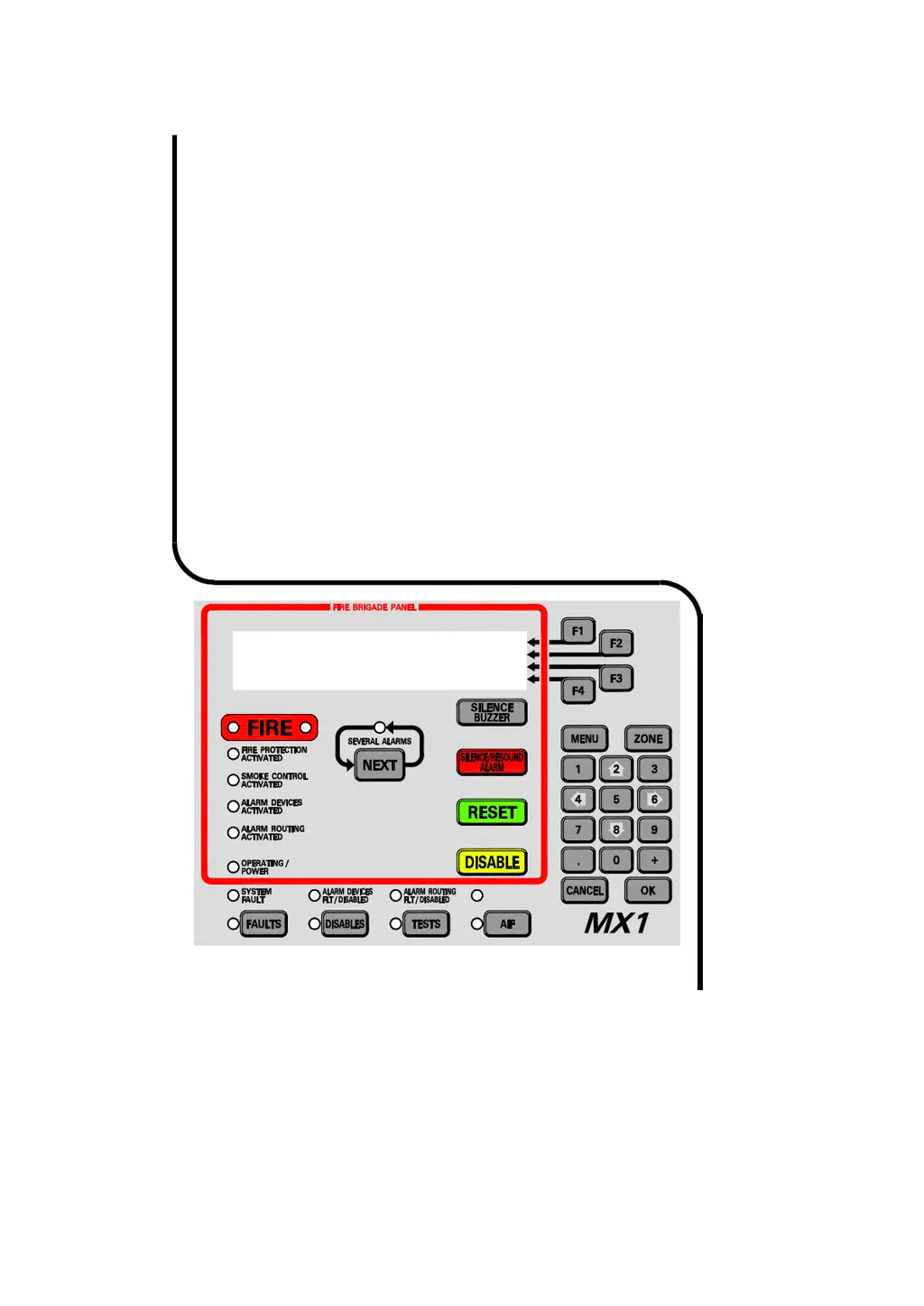
    What to do if Vigilant MX1-Au Button LED flashes but does not change state?
    • D
      Dennis ZamoraSep 10, 2025
      If the button LED flashes but does not change state, it means communication between the DSS master and the MX1 main board or network communications with the remote DSS controls have failed. Check the communication cable from the master control board to the MX1 main board. Check the network communications if the control is a ‘Duplicate’.
  • A
    Anthony ManningAug 25, 2025
    What to do if Vigilant MX1-Au Fire Alarms panel has no lights or LCD activity?
    • L
      Laura BarkerAug 25, 2025
      If there are no lights or LCD activity when the panel's main power switch is turned on and the PSU power light is off, check the mains power at the supply and the mains connection to the panel. Also, check that the PSU plug is connected and powered on. Ensure the battery is charged, and inspect the mains supply fuses at the switchboard, replacing them if necessary.
  • R
    Ricky HillAug 25, 2025
    Why is the Vigilant Fire Alarms POWER ON LED flashing?
    • C
      Carl StokesAug 26, 2025
      The POWER ON LED flashes when the mains power is off or has failed. Check the mains supply. If the mains supply is present, verify that the MX1 PSU is functioning correctly.
  • D
    drodriguezSep 23, 2025
    What does PreAlarm mean on Vigilant Fire Alarms?
    • L
      Lisa WalkerSep 23, 2025
      If your Vigilant Fire Alarms system indicates a 'PreAlarm' condition, it means that one of the points mapped to the zone is in pre-alarm. Use the history display or the off-normal recall menu to identify which point is in pre-alarm. You can also check the analogue values of the point in pre-alarm using the values menu.
  • P
    ptaylorSep 10, 2025
    How to fix Vigilant MX1-Au '245.248.x' points in fault?
    • B
      benjamin16Sep 12, 2025
      If “245.248.x” points are in fault, it indicates that point 245.248.0 fault is “Common Scan Fail,” meaning one or more AS1668 control boards configured on the DSS are not communicating with the DSS master board. Check the dip switch on the board to ensure a unique odd number is assigned/used and matches the SmartConfig configuration.
  • J
    Justin AlexanderSep 15, 2025
    What does ERROR: UNABLE TO RECEIVE CONFIG DATA mean on Vigilant MX1-Au Fire Alarms?
    • B
      Brittany BrownSep 15, 2025
      If your Vigilant Fire Alarms system shows 'ERROR: UNABLE TO RECEIVE CONFIG DATA', it means the LCD/Keyboard communications are working, but the Controller won't send a valid configuration message to the Keyboard. This is likely because the LCD/Keyboard and Controller board firmware versions are incompatible. You should install compatible firmware versions in both the LCD/Keyboard and Controller. Contact your service company for assistance.
  • L
    laurahartSep 4, 2025
    How to fix Vigilant Fire Alarms Alarm Devices Fault/Disabled LED when it's on steady?
    • D
      Daniel JohnsonSep 4, 2025
      If the Alarm Devices Fault/Disabled LED is on steady, it means alarm devices have been disabled. Press the Disables key to determine whether Alarm Devices have been disabled from the panel.
  • M
    Mary MooreSep 5, 2025
    What to do if Vigilant Fire Alarms Controller board or keypad 'RAM Test' points are in fault?
    • T
      tammy25Sep 5, 2025
      If the Controller board or keypad “RAM Test” points are in fault and the Fault LED (Controller LD1) is on, it indicates faulty hardware. Replace the Controller.
  • G
    gmontgomerySep 23, 2025
    What does Zone not configured in database mean on Vigilant MX1-Au?
    • J
      Jason RogersSep 23, 2025
      If your Vigilant Fire Alarms system displays 'Zone not configured in database', it means the SID specified by the zone number that has been entered does not appear in the list of SIDs in this panel’s configuration database. If you need to recall a zone from the specified SID from this panel, you need to add the SID to the configuration data file.
  • M
    Maurice GreeneAug 29, 2025
    What causes Vigilant MX1-Au Fire Alarms internal sounder to sound continuously?
    • B
      Brianna GlennAug 30, 2025
      If the internal sounder sounds continuously with no fault present, it indicates a hardware fault. Replace the LCD/Keyboard.

Summary

Chapter 1 Introduction

How to Use this Manual

Provides instructions on operating the MX1 panel and understanding its displays and conventions.

System Operation

Describes the core functions and capabilities of the VIGILANT MX1 fire detection system.

Operator Access Levels

Details the different access levels and their associated command permissions.

Chapter 2 Managing Alarm Conditions

Handling Alarms Using the Fire Brigade Panel

Step-by-step guide for managing alarms using the Fire Brigade Panel (FBP) controls.

Viewing Alarms

Explains how the MX1 indicates alarm presence and displays alarm details.

Resetting Alarms in the Alarm List

Procedures for resetting alarms after investigation and clearing conditions.

Chapter 3 Managing Faults and Disables

Viewing Faults

Describes how the MX1 indicates faults and how to view fault details.

Viewing Disables

Explains how to view disabled items (zones, points) and their status.

Chapter 4 Viewing the Event History

Viewing Event History

Details how to access and interpret the MX1's event history log.

Zone Events

Describes the format and meaning of zone-specific event messages.

Point Events

Explains the format and meaning of point-specific event messages.

Chapter 5 Recalling Zone and Point Status

Recalling Off-Normal Points and Zones

Guides on recalling and viewing the status of off-normal points and zones.

Chapter 6 Zone and Point Functions

Resetting Zones or Points

Procedures for resetting zones and points to clear alarm or fault states.

Disabling and Enabling Points or Zones

Instructions for disabling or enabling individual or ranges of points/zones.

Testing Zones

Details on performing various tests on zones, including alarm and fault tests.

Chapter 7 Logging On to Access Level 3

Logging On to Access Level 3

Step-by-step guide to access critical service functions using User Code and PIN.

Chapter 8 Other Service Functions

Power Supply Status and Battery Testing

Checking power supply voltage, current, and battery status.

MX Loop Status

Monitoring the voltage and current status of MX addressable loops.

Replacing an MX Device

Procedures for replacing MX devices and automatic re-addressing.

Commissioning Mode (Access Level 3)

Enabling commissioning mode to reduce detector test times.

Resetting the System (Access Level 3)

Restarting the MX1 panel from the LCD, requiring Access Level 3.

Chapter 9 Networking

Tandem Mode

Allows remote panel operation as if standing in front of it via the network.

Network Comms Status

Displays communication status of network interface devices.

Network Fault Status

Shows status of network faults, including path and communication failures.

Chapter 10 Buzzer Cadences, LCD Error Messages and Fault Finding

Troubleshooting - LCD Messages and Actions

Provides a guide to interpreting LCD messages and taking corrective actions.

Chapter 11 Mounting and Wiring Instructions

Cabinet Installation

Instructions for installing the MX1 panel within its cabinet.

Mains Wiring

Details on connecting the dedicated mains feed to the MX1 cabinet.

Battery Wiring

Guidance on connecting batteries for system standby power.

MX Addressable Loop Wiring

Instructions for wiring MX addressable devices to the MX1 controller.

Initial Power On

Steps for the initial power-up sequence and basic checks.

Chapter 12 Specifications

General Specifications

Provides overall technical specifications for the MX1 system.

MX1 Analogue Loop Compatible Devices

Lists devices compatible with the MX1 analogue loop.

Equipment Point Descriptions

Detailed descriptions of all in-built points and their functions.

Vigilant MX1-Au Specifications

General IconGeneral
BrandVigilant
ModelMX1-Au
CategoryFire Alarms
LanguageEnglish