Vigilant MX1-Au Operator Manual Document: LT0439
Page 23 October 2018 Issue 1.73
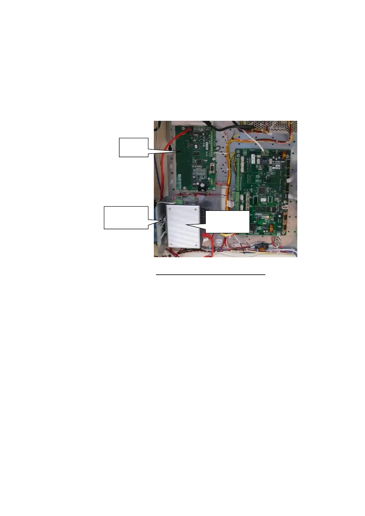
Note the Moxa switch needs to be earthed to the cabinet via the earth
screw on its top, and the Ethernet extender requires 10mm of clear air
around it for ventilation.
It is also possible to mount the PIB and the FP1012 in the same position
to allow room for other devices such as MX Loop Cards. But in this case
only the Moxa switch or an Ethernet Extender can be mounted on the
FP1012 bracket and the PIB LEDs will not be visible.
Figure 11-33 – PIB Mounting Example
Note: When using fibre cabling you must allow for cable entry and
minimum bend radius in deciding the fibre cable route to the switch
(commonly 60-90mm for field cables, 40mm for patch leads).
The MX1 is shipped with a factory default configuration loaded. This
configuration inverts some fault conditions (e.g., no ELD on Anc 3 is
normal) to allow the system to be normalised and causes some relays to
turn on or off every 30 seconds. It is not suitable for general use.
Temporarily disconnect all field wiring, if connected, and switch the MX1
mains switch on.
The green “POWER” LED on the controller should light, and the yellow
“B” and “C” LEDs should flash.
The LCD/keyboard will beep, and the LCD will display its firmware
version number briefly before changing to the MX1 display.
Two faults will be generated – battery low and battery fail. Short the
BATT CONN link Lk3 on the controller – LD6 should turn on and the
faults go away.