Vigilant MX1-Au Operator Manual Document: LT0439
Page 23 October 2018 Issue 1.73
AS 1668 Fan Controls are mounted in MX1 panels by using MX1
AS 1668 3U 19” rack doors (FP1056) that come with 2 fan controls fitted.
Each door can accommodate 12 controls in total by the addition of five
FP1057 Fan Control Expansion Kits. Each kit provides 2 fan controls.
The MX1 panel can support up to 126 fan controls (63 boards), although
additional cabinets will be required for more than 36 controls in a 15U
cabinet.
Installation of the MX1 Fan Controls is detailed in the MX1 Fan Controls
Install Instructions (LT0587). A copy of LT0587 is included with every
FP1056 MX1 Fan Control 3U 19” rack door and FP1057 MX1 Fan
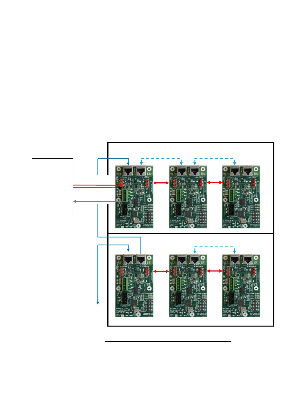
Controls expansion kit. Wiring is shown in Figure 11-8.
Figure 11-8 –
MX1
Fan Control Boards Wiring Diagram
The DIP switch on each fan control needs to be set to a unique odd
number from 1 to 125. All controls must have their ‘M’ switch set to ON
except the Master control which has the ‘M’ switch set to OFF.
MX1
Controller or
MX Loop
Card
Loop Interface
Supply J33