Document: LT0439 Vigilant MX1-Au Operator Manual
Issue 1.73 23 October 2018 Page 11-9
The detectors plugged into an isolator base (4B-I or 5B-I) or
on the spur connection of the line isolator module (LIM800)
are not affected by a short circuit on either side of the
isolator. 850 series detectors have built-in short circuit
isolators if fitted to 4B-C bases.
Each device in parallel on an input or output module should
be counted as one device.
Refer to the installation instructions supplied with the MX devices for their
wiring details, or to LT0442 MX1-Au Field Wiring Instructions.
F
IR
E
D
E
F
N
C
2
C
2
N
O
2
MX1 CONTROLLER
N
C
2
C
2
N
O
2
AR-
BRIGADE SIGNALLING
INTERFACE
ASE+
0V
ASE
INTERFACE
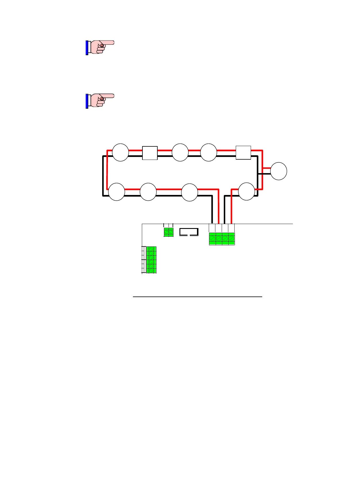
Detector
DetectorDetector
Detector
Detector
Detector Detector
Module
Module
Detector
AR+
AL-
AL+
Figure 11-7 – Addressable Devices on
MX
Loop
It is strongly recommended that the cabling requirements should be
calculated for each installation. The MX1Cost program can be used for
this purpose.
Additional MX Loop Cards (order as FP0950) can be installed to provide
more MX loops of up to 250 devices each, up to the system limit.
The MX Loop Card links and DIP switch must be set during installation.
Full installation instructions are contained in LT0443, “MX1 Loop Card
Installation Guide”.
There is a range of brackets available for mounting MX modules in the
MX1 panel – usually positioned where the MX Loop Cards mount. Refer
to the relevant installation instructions LT0557 and LT0591.