Vigilant MX1-Au Operator Manual Document: LT0439
Page 23 October 2018 Issue 1.73
pre-punched holes or saddles for fitting trunking to the gear plate, for
fitting the supplied push-fit cable tie mounts, and for looming using
cable ties directly to the gearplate.
The MX1 cabinet is designed to be easily surface mounted on a wall or
inset in a wall cavity.
The cabinet location should:
Be dry, with a moderate ambient temperature, 45°C absolute
maximum.
Not be subject to outdoor conditions without suitable protection.
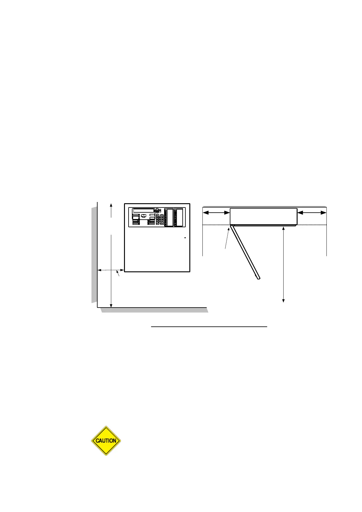
Allow the LCD to be at typical eye level (see Figure 11-1).
Have clear access and viewing for fire firefighters and operators.
Allow for the door to open at least 120°.
The cabinet must not be installed in hazardous areas as defined in
AS/NZS 3000.
Fire Alarm
System
MX
1
1 m
1300 to
1850
mm
Finished floor level
Rear wall
Cabinet
can be
flush
mounted
Side
wall
Side wall
At least
600 mm
Side
wall
600mm600mm
MX1
Figure 11-1 – Recommended clearances
The cabinet is supplied predrilled with four keyholes suitable for mounting
screws of not more than 8mm shaft diameter and 11mm head diameter.
A drilling template is supplied with each unit. Refer Figure 11-2 and 11-3.
The cabinet has two knockouts in the back of the cabinet. One ø20mm
knockout is behind the mains socket and a larger oval knockout is behind
the slot in the gearplate. See Figures 11-2 and 11-3.
If any drilling or filing is required inside the cabinet, it is
recommended to first remove the gear plate containing the
PCBs and power supply. Unplug the MCP/door switch loom
(from J3) and the 10-way loom from the LCD/keyboard (from
J30) before removing the gear plate.
Wall Mounting – 8U / 15U Cabinet