Installation Guide MX1 Fire Alarm System (NZ)
LT0360 ISSUE 2.43 29 NOVEMBER 2017 PAGE 20
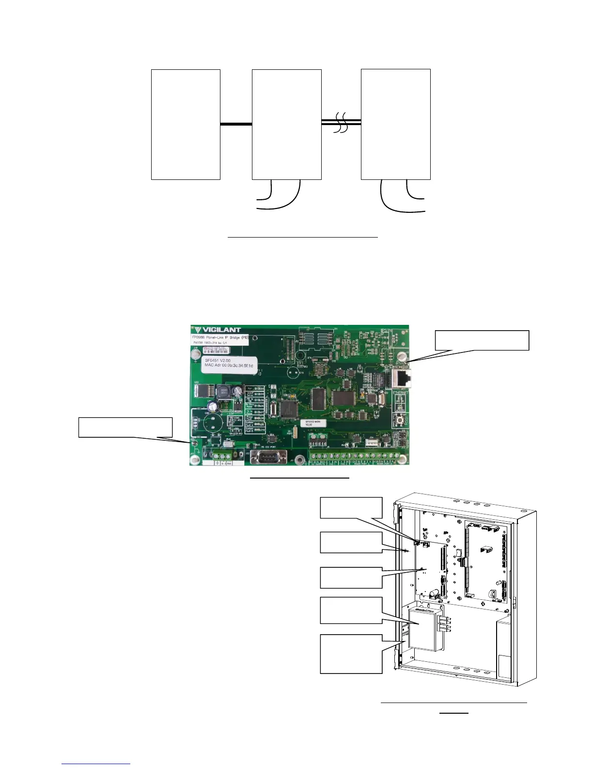
See Figure 31 for wiring, and refer to the PIB User Manual (LT0519) for configuring the Ethernet Extenders as “CO”
(Central Office) or “CPE” (Customer Premises Equipment).
Figure 31 – Ethernet Extender Wiring
PIB Mounting
The PIB (FP0986) is required to be earthed and the recommended earthing method is via 2 metal standoffs (J17
and J19) in the positions shown in Figure 32. The other standoffs may be plastic or metal. If J17 and J19 are not
earthed this way, then earth leads (included with the PIB) must be fitted to the adjacent earth tabs J23 and J25, with
the leads electrically connected to the gearplate/cabinet earth.
Figure 32 – PIB Earthing
Slimline Cabinet
The PIB is mounted on the 5 plastic standoffs and 1 metal
standoff on the left side of the gear plate as shown in Figure
33.
An Earth loom must be connected between the J25 Earth
tab (top left) on the PIB to the Earth stud on the left side of
the cabinet.
A Moxa switch and one Ethernet extender (or 2 Ethernet
extenders) can be mounted using one FP1012 mounting
bracket. This bracket is mounted using 4 screws as shown
in Figure 33.
Note: The Moxa switch needs to be earthed to the cabinet
via the earth screw on its top, and the Ethernet extender
requires 10mm of clear air around it for ventilation.
Note: When using fibre cabling you must allow for cable
entry and minimum bend radius in deciding the fibre cable
route to the switch (commonly 60-90mm for field cables,
40mm for patch leads).