Installation Guide MX1 Fire Alarm System (NZ)
LT0360 ISSUE 2.43 29 NOVEMBER 2017 PAGE 14
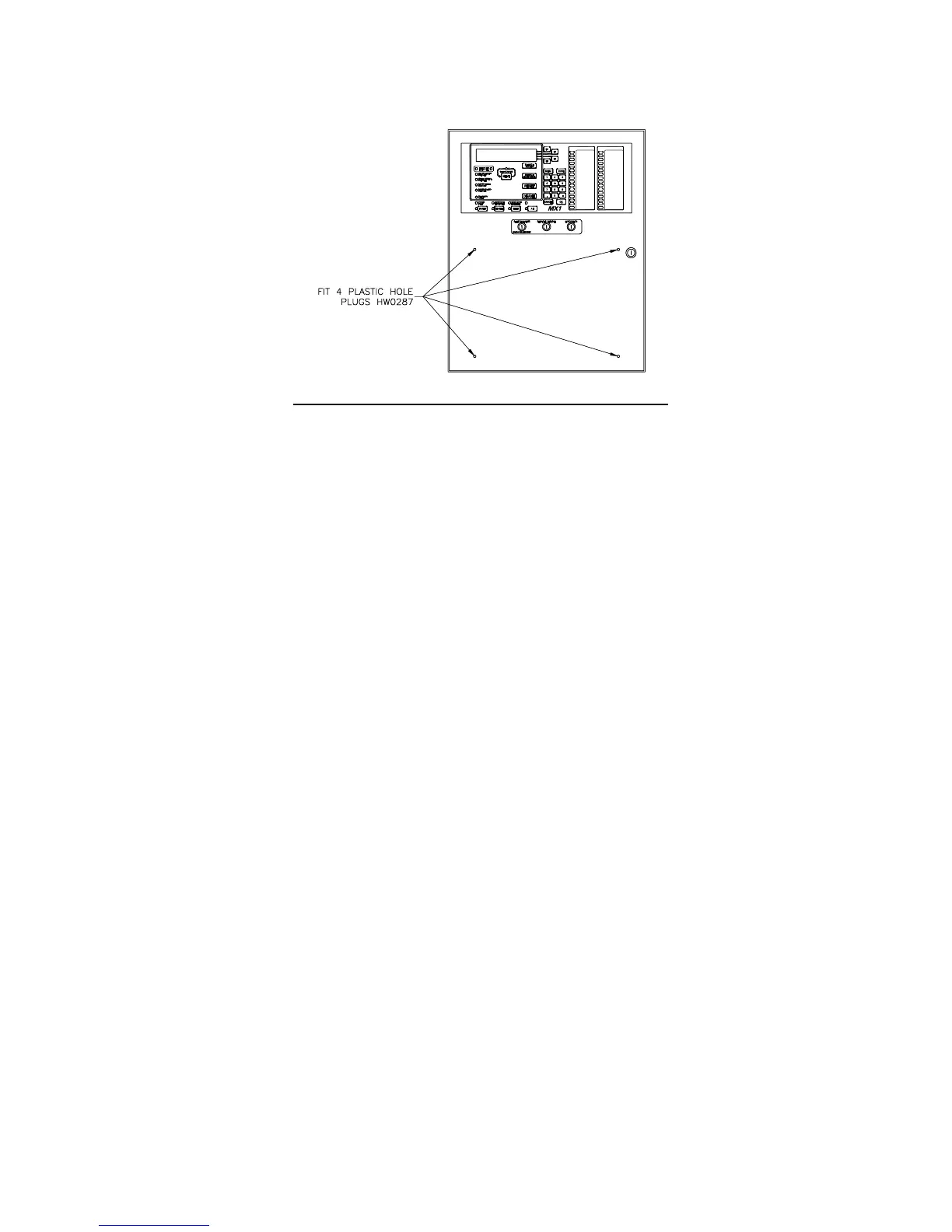
Plastic push-in blanking plugs (HW0287) are also supplied with the MX1. These are a press-fit into the front door
index mounting holes when a front service index is not required. Refer Figure 20. 15U cabinets will generally
require a separate index and zone display unit for brigade use.
Figure 20 – Positions of Push-in blanking plugs (HW0287)
Rear Service Slimline Cabinet
Zone displays in a rear service format are labelled by engraving the rear service index. The rear service index,
supplied with each MX1 Slimline cabinet, can be removed by removing the internal gear plate holding the controller
and other circuit boards. See page 3 for details of removing the gear plate.
Blank strips from LB0600 may be slipped into the unused front panel zone display positions to hide the holes and
fasteners in the panel.
MX Loop Card
The installation of the MX Loop Card is detailed in the MX1 Loop Card Install Instructions (LT0443). A copy of
LT0443 is included with every FP0950 MX Loop Card kit.
Remote Fire Brigade Panel (RFBP)
The MX1 Remote FBP is powered by and communicates with the MX1 panel. Installation and wiring of the RFBP is
described in LT0545, supplied with each RFBP.
MX1 15U Cabinet
Additional installation and wiring information is contained in the MX1-Au Fire Alarm System – Wiring Diagrams
(LT0442). Note that some information in LT0442 is Australian-specific.
MX1 Networking
MX1 panels can be networked together in a variety of ways normally using copper data cable or fibre optic cable.
Depending on the system design requirements the network interface will either be Intelligent Hubs (I-HUBs) or
Panel-Link IP Bridges (PIBs). I-HUBs are usually interconnected in a ring using RS485 data copper cable, but can
also be interconnected with fibre optic cable with the addition of OSD139 Fibre Optic modems. PIBs are usually
used with Fibre Optic switches, Ethernet Extenders, or shielded Ethernet (STP) cables. This section covers the
most common applications and includes the mounting of the I-HUB and PIB in the NZ Slimline and 15U cabinets,
the wiring between the I-HUB / PIB and the MX1 Controller board, and the mounting and wiring of OSD139 Fibre
Optic modems for use within I-HUB and the mounting and wiring of Moxa Fibre Optic Ethernet switches for use with
the PIB.